<?xml version="1.0" encoding="utf-8"?><feed xmlns="http://www.w3.org/2005/Atom" ><generator uri="https://jekyllrb.com/" version="3.10.0">Jekyll</generator><link href="http://www.sandinbrain.com/feed.xml" rel="self" type="application/atom+xml" /><link href="http://www.sandinbrain.com/" rel="alternate" type="text/html" /><updated>2026-05-19T06:58:53+00:00</updated><id>http://www.sandinbrain.com/feed.xml</id><title type="html">sandinbrain</title><subtitle>Blog about whatever damned thing has cut my finger this time.</subtitle><entry><title type="html">Sheldon Lathe Headstock Gear</title><link href="http://www.sandinbrain.com/2026/04/09/sheldon-lathe-headstock-gear.html" rel="alternate" type="text/html" title="Sheldon Lathe Headstock Gear" /><published>2026-04-09T00:00:00+00:00</published><updated>2026-04-09T00:00:00+00:00</updated><id>http://www.sandinbrain.com/2026/04/09/sheldon-lathe-headstock-gear</id><content type="html" xml:base="http://www.sandinbrain.com/2026/04/09/sheldon-lathe-headstock-gear.html"><![CDATA[<p>A quick one today. The gear that transmits power to the carriage feed for turning/threading on the Sheldon MW56P is missing a couple of teeth.</p>

<p>Unfortunately, in my zeal to get this machine cleaned up and operational I did not get any pictures of the gear train with its 20 years of undisturbed old oil caked on there. The grime was so great that I originally believed this gear to be iron.</p>

<p>You can imagine I was quite disappointed to find this, as I do not have gear cutters, nor a milling machine for that matter. I had then resolved to simply 3D print the gear.</p>

<p>After pulling the gear, it was submerged with its brethren in the parts washer for the night and scrubbed clean the next day. It’s micarta with a pressed in brass bearing! (The manual calls it out as a “Formica” gear.) Really was a pleasure to see this.</p>

<p><img src="/assets/img/sheldon/broken_headstock_gear.webp" alt="Broken Headstock Gear" /></p>

<p><img src="/assets/img/sheldon/reverse_plate_parts_list.png" alt="Reverse Gear from Parts List" /></p>

<p>Its twin, the forward feed gear is brass. It seems that the second gear was chosen to be the sacrificial piece should the carriage crash as it is engaged regardless of whether one is feeding right or left.</p>

<!-- Insert image of right-left selection -->

<p>There is one more Formica gear in the assembly, connecting the selector gearing assembly to the feed ratio gearbox (which will get its own article). These Formica gears do more than offer break points in crash scenarios– they quiet the geartrain considerably, anyone that’s heard a straight cut gear transmission can attest.</p>

<!-- Insert image of end gearing irl -->
<p><img src="/assets/img/sheldon/end_gearing_assembly_parts_list.png" alt="End Gearing Assembly" /></p>

<p>Anyhow, some measurements with the calipers and some educated guessing (later confirmed) led me to believe the gear was 16 Diametral Pitch with a 14.5 degree pressure angle.</p>

<center><img src="/assets/img/sheldon/scratchpad_gear_1.jpg" /></center>

<p>I made this part during the week or so I was trying out Onshape (6.5/10, undercooked) and the spur gear creator tools makes the bulk of the work trivial.</p>

<p>The gear features some bosses that position it laterally on its shaft– just some raised profiles with a chamfer.</p>

<p><img src="/assets/img/sheldon/onshape_gear.gif" alt="Gear Model in Onshape" /></p>

<p>Now came the issue of the bushing. I could certainly mail order some bronze bushings from McMaster-Carr, or even bronze stock, but why bother when I can simply drive 1 mile to Lowe’s and pick up cheap self-lubricating bronze bushings?</p>

<p>And that’s what I did. I brought two home with me and modeled a “press-fit” (hard push into the desk) bore into the part to match.</p>
<blockquote>
  <p>Notice the measurement of the bore shrink in the scratchpad image!</p>
</blockquote>

<center><img src="/assets/img/sheldon/scratchpad_gear_2.jpg" /></center>

<p>Of course, the bushing bore does not match the the shaft diameter, but this was anticipated; I planned to machine the bores on the lathe before installation to ensure a perfect fit. Machining these self-lubricating bushings is always annoying– can’t really gronk on it in the chuck, there’s sticky bronze dust everywhere, a “good” surface finish probably means you’ve smeared the pores shut. I machined it in a collet to avoid crushing the sintered structure. I am willing to live with the third point, as the bushing is oiled internally via Gits cup. There is now forevermore bronze dust in the lathe.</p>

<p><img src="/assets/img/sheldon/end_gearing_assembled_2.jpg" alt="Installed Gear" /></p>

<p>Unfortunately, at some point while taking this apart I lost one of the washers. <em>If only I had a lathe, I could just make a new one ;)</em></p>

<p>Anyhow, the feed ratio gear box still needs work before I really can use the power feed or do any threading, so that’s next on the list.</p>]]></content><author><name></name></author><category term="tools" /><category term="shop" /><category term="machining" /><category term="lathe" /><category term="Onshape" /><category term="3D printing" /><category term="sheldon" /><summary type="html"><![CDATA[A quick one today. The gear that transmits power to the carriage feed for turning/threading on the Sheldon MW56P is missing a couple of teeth.]]></summary></entry><entry><title type="html">Boring Bar Holder Adapter</title><link href="http://www.sandinbrain.com/2026/04/08/boring-bar-holder.html" rel="alternate" type="text/html" title="Boring Bar Holder Adapter" /><published>2026-04-08T00:00:00+00:00</published><updated>2026-04-08T00:00:00+00:00</updated><id>http://www.sandinbrain.com/2026/04/08/boring-bar-holder</id><content type="html" xml:base="http://www.sandinbrain.com/2026/04/08/boring-bar-holder.html"><![CDATA[<p><strong>A Solemn Promise: No boring/boring puns will be made in this article, or any others hereafter.</strong></p>

<p>As I mentioned in the <a href="/tools/shop/2026/04/01/sheldon-lathe-acquisition.html">acquistion article</a>, the 10mm shank carbide insert tooling I bought fits in most of my toolholders, except for (what I believe is) the boring bar holder. It is a typical clamping style holder, a 3/4” bore with a slit and socket head cap screws to tighten it up.</p>

<blockquote>
  <p>I didn’t take any pictures while making this so you’ll see the finished part the entire time.</p>
</blockquote>

<p>The toolholders cleaned up pretty nicely in the Evaporust bath.</p>

<p><img src="/assets/img/boring_bar_holder/toolholder.jpg" alt="The Toolholder" /></p>

<blockquote>
  <p>I typically clean off the carbon film left by the Evaporust with a brass wire brush, but this leaves a golden cast on the surface. It comes off fairly easy with Scotchbrite, or even the big wire wheel, but I hate extra steps.</p>
</blockquote>

<h2 id="i-suspect-this-thin-shank-will-chatter-quite-a-bit-taking-a-big-cut-but-a-small-boring-bar-retains-its-utility-late-into-a-machinists-life">I suspect this thin shank will chatter quite a bit taking a big cut, but a small boring bar retains its utility late into a machinist’s life.</h2>

<p><img src="/assets/img/boring_bar_holder/boring_bars.jpg" alt="10mm Boring Bar" /></p>

<p>I briefly considered 3D printing a part but this is a simple enough problem to solve for a man with a lathe. All I need to do is turn a cylinder to fit the boring bar holder and bore it out to fit the boring bar holder. In fact, it is such a simple part I did absolutely zero planning. I spent longer finding a piece of stock to turn this out of than I did thinking about how I was going to make it.</p>

<p>I found a piece, something like 1-3/8” in diameter and fairly clean, an offcut from a tilt lock pin for a fifth wheel I made earlier this week.</p>

<p><img src="/assets/img/boring_bar_holder/1_38_stock.jpg" alt="1-3/8 Stock" /></p>

<p>Large boring operations typically relieve the worst of the internal stresses in the material and cause warping so it’s best to do that before the outer diameter. Thankfully, I have a 10mm drill (literally my only metric drill) that will get us close enough for the fit on the boring bar shank.</p>

<p><img src="/assets/img/boring_bar_holder/drilling.jpg" alt="10mm Bore" /></p>

<p>The surface finish from the drill is not the best, but the holder needs only hold the bar statically, so no worries.</p>

<p>I turned the stock roughly to diameter before upping the RPM and taking light cuts until the holder slips on nicely. The surface finish is quite admirable from this brand new insert.</p>

<p><img src="/assets/img/boring_bar_holder/shank.jpg" alt="Shank Adapter" /></p>

<blockquote>
  <p>The flash makes this look worse than it actually is.</p>
</blockquote>

<p>At this point, I was still holding on to the excess stock in the chuck, mill scale and all and turned it around intending to part it into a simple cylinder. But pulling it out and looking at it, I thought it’d look quite attractive with a nice flange. I parted the end to a suitable thickness and stuck a hefty chamfer onto it.</p>

<p><img src="/assets/img/boring_bar_holder/facing.jpg" alt="Shank in Chuck" /></p>

<blockquote>
  <p>I hate parting, I’m always scared and inevitably I get a terrible surface finish. I took one or two cleanup passes but left some of the scarring as a “parting gift.”</p>
</blockquote>

<h2 id="the-flange-has-an-additional-benefit-of-locating-the-adapter-to-the-proper-depth-in-the-holder">The flange has an additional benefit of locating the adapter to the proper depth in the holder.</h2>

<div style="display: flex;">
  <img src="/assets/img/boring_bar_holder/located1.jpg" style="width: 50%;" />
  <img src="/assets/img/boring_bar_holder/located2.jpg" style="width: 50%;" />
</div>
<p><br /></p>

<p>Now that the adapter was turned, I had to finally consider how I was going to hold the boring bar in the holder. The bar it self has a flat for set screws to touch down on and I do not have a slitting saw, or so much as a mill that would hold it, to make a clamping mechanism, so set screws it is. I scribed a line with the carriage to mark where I’d drill.</p>

<p>I’ve no drill press vise but this corner clamp vise works fairly well. I drilled and tapped some 1/4”-28 holes and put in some 1/4” long set screws.</p>

<p><img src="/assets/img/boring_bar_holder/drilling_vise.jpg" alt="Adapter in Vise" /></p>

<p>Unfortunately they protrude a bit, so I thought I’d just turn the length to about 3/16”, maybe a little less. Unfortunately, the screws were a little too large for a 7/32” collet and too small for a 1/4” collet. There was simply no way to hold them properly in the chuck. I guess I could have just touched them on the grinder, there was only a 1/16” to take off, but I could not stand not having that gnarled, burred face inside my part. 
So, I overnighted some off of Amazon and went on my merry way.</p>

<h2 id="all-done">All done:</h2>

<p><img src="/assets/img/boring_bar_holder/finished.jpg" alt="Finished" /></p>]]></content><author><name></name></author><category term="tools" /><category term="shop" /><category term="machining" /><category term="lathe" /><summary type="html"><![CDATA[A Solemn Promise: No boring/boring puns will be made in this article, or any others hereafter.]]></summary></entry><entry><title type="html">I Am Now the Proud Owner of a Lathe.</title><link href="http://www.sandinbrain.com/2026/04/01/sheldon-lathe-acquisition.html" rel="alternate" type="text/html" title="I Am Now the Proud Owner of a Lathe." /><published>2026-04-01T00:00:00+00:00</published><updated>2026-04-01T00:00:00+00:00</updated><id>http://www.sandinbrain.com/2026/04/01/sheldon-lathe-acquisition</id><content type="html" xml:base="http://www.sandinbrain.com/2026/04/01/sheldon-lathe-acquisition.html"><![CDATA[<blockquote>
  <p>This article is dated to reflect the time of development/completion, not writing.</p>
</blockquote>

<blockquote class="twitter-tweet"><p lang="en" dir="ltr">I am now the proud owner of a lathe</p>&mdash; central valley odysseus (@sandinbrain) <a href="https://twitter.com/sandinbrain/status/2039585488001274345?ref_src=twsrc%5Etfw">April 2, 2026</a></blockquote>
<script async="" src="https://platform.twitter.com/widgets.js" charset="utf-8"></script>

<p>Yes.</p>

<p>A Sheldon MW56P. Swings 13”. 56” bed. 2HP.</p>

<p>Take a look at that.</p>

<p><img src="/assets/img/sheldon/sheldon.jpg" alt="Lathe Picture" />
<img src="/assets/img/sheldon/sheldon2.jpg" alt="Lathe in Place" /></p>

<p>$500.</p>

<p>Collets. Hardinge. Draw Bar.</p>

<p><img src="/assets/img/sheldon/collets_and_centers.jpg" alt="Collets out of the EvapoRust" /></p>

<p>Chucks.</p>

<p><img src="/assets/img/sheldon/4jaw_partial.jpg" alt="Four-Jaw Chuck" />
<img src="/assets/img/sheldon/installed_3jaw_rusty.jpg" alt="Three-Jaw Chuck" /></p>

<p>Drill Arbors. 20yo Grease.</p>

<p><img src="/assets/img/sheldon/collet_organizer_w_arbors.jpg" alt="Collet Organizer and Drill Arbors" /></p>

<p>Ok, that’s enough of that, cut the applause, enough fanfare.</p>

<p>The thing needs a lot of work. There’s a broken headstock gear. The carriage doesn’t like to move past about halfway across the bed. The belts smell like burning tires above 1000 rpm. Everything within a foot of the chuck is covered in a solid 1/8” of caked grease and chips.</p>

<p>It was sitting in the garage of some hick (fondly) in the Sierra Nevada Hills, who said that he’d hauled it up from a machine shop closing up in Los Angeles 20 years ago and parked it there; “it ran when I parked it.”</p>

<p><img src="/assets/img/sheldon/original_slumber_place.jpg" alt="Damdama" /></p>

<p>He’d listed it for $650, and I shot him an offer for $500, accepted. I rented a drop bed trailer from Sunbelt for $110 and pulled it up with a come-along with a nasty burr that sliced my thumb.</p>

<p><img src="/assets/img/sheldon/moved_lathe.jpg" alt="Staging" /></p>

<p>And 90 miles back home. I got it in the shop and left for 3 days to Seattle. By the time I got back, my VEVOR Digital Phase Shifter had arrived– a very trust inspiring $75– that does in fact start up the machine perfectly well after some buzzing (I only tripped the breaker once wiring it). I will eventually put this in a cabinet so the terminals and electronics are not exposed to the elements.</p>

<blockquote>
  <p>Here’s a picture of the starter cabinet, still with the original input cord. This picture is also illustrative of the grime collected on the sides of the cabinet. This is a reversing starter, which means there’s actually two different starters, with the one on the left wired opposite the right. Notice the wires leading to the transformer on the left. This is a stepdown transformer that controls a 1RPM gear motor on the rear that changes the drive ratio.</p>
</blockquote>

<p><img src="/assets/img/sheldon/original_control_cabinet.jpg" alt="Starter Cabinet" /></p>

<blockquote>
  <p>I put red and black (plus ground) of the original cord (generous, 6-4 and maybe 20 ft long) on to the Line and Neutral inputs of the phase convertor and the other end to a NEMA 6-50P plug. Figuring out how to connect the phases was confusing until I noticed the V and W on the bottom of the right coil.</p>
</blockquote>

<p><img src="/assets/img/sheldon/VEVOR_DPS.jpg" alt="VEVOR Digital Phase Shifter" /></p>

<p>The lathe came with quite a few accoutrements, many of them quite “premium”, but owing to its age, the actual tooling offerings are subpar: chipped brazed carbide and some fairly good HSS tools, including a very nice parting tool. The compound is equipped with a KDK QC tool post, and a number of toolholders.</p>

<p><img src="/assets/img/sheldon/KDK_toolpost.jpg" alt="KDK Tool Holder" /></p>

<p>The toolholders are made to hold HSS blanks, and are thus undersized for the larger shanks of modern carbide insert holders. Some of them have been milled out to accommodate the larger shanks of some of the old brazed carbide tooling, but again-insufficient length for modern tooling.</p>

<p>I’ve picked up some Amazon-special 10mm shank tooling, a little undersized perhaps but fine for $40. The boring and internal threading bars are also 10mm shank, much too small for what I think is the boring bar holder.</p>

<p>I’ve also picked up some toolboxes on Marketplace, one of which I’ve selected to hold the lathe tooling and other accoutrements.</p>

<p>Anyhow, this will inevitably be a wellspring of projects, many of which I foresee myself not completing for years.</p>
<h3 id="stay-tuned">Stay tuned.</h3>]]></content><author><name></name></author><category term="tools" /><category term="shop" /><category term="machining" /><category term="lathe" /><category term="sheldon" /><summary type="html"><![CDATA[This article is dated to reflect the time of development/completion, not writing.]]></summary></entry><entry><title type="html">Protracted People’s Poplar Project</title><link href="http://www.sandinbrain.com/2026/03/26/poplar-shoe-cabinet.html" rel="alternate" type="text/html" title="Protracted People’s Poplar Project" /><published>2026-03-26T00:00:00+00:00</published><updated>2026-03-26T00:00:00+00:00</updated><id>http://www.sandinbrain.com/2026/03/26/poplar-shoe-cabinet</id><content type="html" xml:base="http://www.sandinbrain.com/2026/03/26/poplar-shoe-cabinet.html"><![CDATA[<p>Last November, my sister got married, and in the months long preparations for this event, we had to consider shoe storage. I was asked to build a larger shoe cabinet and I obliged, knowing that there was no way I could complete it to my standards before the date. There, we ended up stacking some 2x12s on some cinderblocks, more than sufficient for the guests. <em>(You can see the state of the cabinet in November later in the article.)</em></p>

<center>
<img src="https://comb.io/HppBgm.gif" />
<p><i> Obligatory Simpsons Clip </i></p>
</center>

<p>It’s a garage cabinet for holding shoes, so I was certainly not going to make it out of hardwood, but I cannot conscience making it out of anything worse than poplar plywood. This stuff is fairly nice to work with. It’s not very dense, so don’t expect it to take a hit well, but it’s uniform and generally void-free.</p>

<p><img src="/assets/img/shoe_cabinet/sandeply.png" alt="Sandeply" /></p>

<p>The extent of the planning on this is this sketch, which allowed me to figure how much lumber I’d need to purchase.</p>

<p><img src="/assets/img/shoe_cabinet/sketch.jpg" alt="Sketch" /></p>

<h2 id="i-started-sometime-around-late-september-2025">I started sometime around late September 2025.</h2>

<p>I started with the carcass, of course. I ripped 1 full sheet of 3/4” into 5 panels, three 16” x 64” and two 16” x 32”. The dimensions were chosen to use the greatest portion of the purchased lumber possible. Four of these pieces will form the outsides of the carcass, and the last 16” x 64” piece ripped in twain forms the rear strechers/nailers.</p>

<h2 id="this-picture-is-from-october-1-2025">This picture is from October 1, 2025.</h2>

<p><img src="/assets/img/shoe_cabinet/carcass_bottom_and_sides.webp" alt="Carcass Initial" /></p>

<p>I opted to dovetail join the carcass, just as a fun experiment in cutting joinery in plywood, and to punish me the Divine cursed me to make <strong>The Mistake</strong>.</p>

<h2 id="this-picture-is-dated-october-2-2025">This picture is dated October 2, 2025:</h2>
<p><img src="/assets/img/shoe_cabinet/the_mistake.jpg" alt="The Mistake" /></p>

<p>After completing the carcass, the project lay dormant for quite a while.</p>

<h2 id="here-it-is-in-a-picture-dated-october-11-2025">Here it is in a picture dated October 11, 2025:</h2>

<p><img src="/assets/img/shoe_cabinet/cleanup1.jpg" alt="Cleanup 1" /></p>

<h2 id="here-it-is-in-the-background-of-another-project-dated-november-3-2025">Here it is in the background of another project dated November 3, 2025:</h2>

<p><img src="/assets/img/shoe_cabinet/looming.jpg" alt="Looming" /></p>

<h2 id="on-january-12-2026-i-swept-the-shop-again">On January 12, 2026 I swept the shop again:</h2>

<p><img src="/assets/img/shoe_cabinet/cleanup.webp" alt="A New Year" /></p>

<h2 id="sometime-between-then-and-february-18-2026">Sometime between then and February 18, 2026…</h2>

<p>I managed to install the backing 1/4” ply and the shelves (plus some bragging for the Instagram story):</p>

<p><img src="/assets/img/shoe_cabinet/carcass_shelves.webp" alt="Shelves" /></p>

<p>Now for the interesting part, the sliding doors. The design is entirely based on <a href="https://www.finewoodworking.com/2004/10/01/sliding-doors-for-furniture">this article</a> from Fine Woodworking, with one caveat. I had already glued up the carcass and there was no way I could easily locate and push the grooving plane inside the finished width, so I added in a poplar strip with the grooves cut by dado stack on the table saw.</p>

<p>Tuning the fit is an essential part of the process if you want smooth movement all the way across the width, especially with something as large a span as this. I can’t count how many times I took the doors out. It can be quite confusing to know where to remove material. I found that rubbing pencil on the inside of the track will leave an imprint on the door rabbet whereever it might bind.</p>

<p>It is difficult to understand the smoothness of this movement without sound, but you’ll just have to imagine it.</p>

<h2 id="here-it-is-all-built-on-february-28-2026">Here it is all built, on February 28, 2026:</h2>
<p><img src="/assets/img/shoe_cabinet/sliding_door.gif" alt="Sliding Door" /></p>

<h2 id="of-course-it-was-not-for-another-month-march-26-2026-that-the-cabinet-would-actually-get-installed-in-its-final-place-in-my-garage">Of course, it was not for another month (March 26, 2026) that the cabinet would actually get installed in its final place in my garage:</h2>
<p><br />
<img src="/assets/img/shoe_cabinet/finished_installed.jpg" alt="Finished and Installed" /></p>

<blockquote>
  <p>Peep the precarious network rack situation. It’s housing a very heavy lead-acid UPS, held in with three screws. This was fairly quickly remedied with some steel shelf brackets.</p>
</blockquote>]]></content><author><name></name></author><category term="tools" /><category term="shop" /><category term="woodworking" /><category term="furniture" /><summary type="html"><![CDATA[Last November, my sister got married, and in the months long preparations for this event, we had to consider shoe storage. I was asked to build a larger shoe cabinet and I obliged, knowing that there was no way I could complete it to my standards before the date. There, we ended up stacking some 2x12s on some cinderblocks, more than sufficient for the guests. (You can see the state of the cabinet in November later in the article.)]]></summary></entry><entry><title type="html">Adapting Switches 2</title><link href="http://www.sandinbrain.com/2026/03/18/tarp-switch-adapter.html" rel="alternate" type="text/html" title="Adapting Switches 2" /><published>2026-03-18T00:00:00+00:00</published><updated>2026-03-18T00:00:00+00:00</updated><id>http://www.sandinbrain.com/2026/03/18/tarp-switch-adapter</id><content type="html" xml:base="http://www.sandinbrain.com/2026/03/18/tarp-switch-adapter.html"><![CDATA[<p>I’ll save you the blurb on this one. Trucks need switch adapters.</p>

<p>This one is for a tarp switch on a MACK CX13 (yes, the same one as last time).</p>

<p>I modeled this during my Onshape phase, and unfortunately they don’t have a built-in embedded viewer, so you’ll have to live with images and a link to the part.</p>

<p>Very similar story to last time.
I modeled the perimeter of the cover and the perimeter of the new switch and printed a test piece.
In this case, the switch body fits the dash’s slot width, just not the height. This is not a problem per se, but we have to make the adapter wider than the original cover width. Thankfully the slots are spaced sparsely enough that we need not worry about overlap.</p>

<p><img src="/assets/img/switch_adapter2/test1.jpg" alt="First Test Print" /></p>

<p>We can then immediately proceed to creating the clasp geometry.
This adapter’s clasp features the same winged geometry as the last one, but I’ve decided to take a different route to modeling it. 
Instead of an extrusion with features being “cut out” of it, we simply loft the end profiles together into the continuous solid of the wing.</p>

<p><img src="/assets/img/switch_adapter2/clasp_geometry.png" alt="Clasp Wing Sketch" /></p>

<p>Unfortunately this switch does not have any reliefs in which to add extra meat to bear on, so we’l have to live with just a central pillar.</p>

<h2 id="all-modeled">All modeled:</h2>
<center><img src="/assets/img/switch_adapter2/modeled.png" /></center>

<h2 id="and-printed">And printed:</h2>
<p><img src="/assets/img/switch_adapter2/test2.jpg" alt="Second Test Print" /></p>

<h2 id="and-installed">And installed:</h2>

<div style="display: flex;">
  <img src="/assets/img/switch_adapter2/installed1.jpg" style="width: 50%;" />
  <img src="/assets/img/switch_adapter2/installed2.jpg" style="width: 50%;" />
</div>

<h2 id="and-in-its-final-resting-place">And in its final resting place:</h2>

<p><img src="/assets/img/switch_adapter2/installed3.jpg" alt="Installed" /></p>]]></content><author><name></name></author><category term="3d printing" /><category term="electrical" /><category term="Onshape" /><summary type="html"><![CDATA[I’ll save you the blurb on this one. Trucks need switch adapters.]]></summary></entry><entry><title type="html">They Did Surgery on a Mouse…</title><link href="http://www.sandinbrain.com/2026/03/15/g604-repair.html" rel="alternate" type="text/html" title="They Did Surgery on a Mouse…" /><published>2026-03-15T00:00:00+00:00</published><updated>2026-03-15T00:00:00+00:00</updated><id>http://www.sandinbrain.com/2026/03/15/g604-repair</id><content type="html" xml:base="http://www.sandinbrain.com/2026/03/15/g604-repair.html"><![CDATA[<p><img src="/assets/img/g604/g604.jpg" alt="G604" /></p>

<p>I love this mouse, the Logitech G604 Wireless, unfortunately discontinued (New old stock going for $300+ online!!!).</p>

<p>I am a middle-clicker, I think I middle click more than the average person, constantly opening things in new tabs, closing tabs, and unfortunately the button has given up. 
I was looking to replace just the actual switch, a very cheap little dome switch, but I could not identify it just from pictures online.</p>

<p>Of course, I did find it post hoc.</p>

<p><img src="/assets/img/g604/dome_switch.png" alt="Dome Switch" /></p>

<p>And of course, I would have to replace the skates as well; this combo of replacement board and skates costs the same as just the skates on Amazon; it’s a clear choice.</p>

<p>This article is not that interesting, I mostly took so many pictures so I would know how to put it back together; there are so many screws, so many small plastic parts; but it might be helpful to someone else taking apart their mouse.</p>

<h2 id="disassembly">Disassembly</h2>
<p>After removing the skates and screws from the bottom, the bottom comes straight off and the top/inner structure can be manuevered out of the side shell by tilting it up.</p>

<p><img src="/assets/img/g604/side_bottom_shroud.jpg" alt="Side and Bottom Removal" /></p>

<p>I probably ought to have removed the ribbon cables before the previous maneuver, but better late than never.</p>

<p><img src="/assets/img/g604/bottom_ribbon.jpg" alt="Bottom w/ Ribbon" /></p>

<p><img src="/assets/img/g604/ribbon_removed.jpg" alt="Ribbon Removed" /></p>

<p>As a little treat you can see the current state of my desk including the mouse I was using while this one is in the OR. In anticipation of this repair I printed a little parts tray in a gaudy tricolor PLA my brother-in-law fished out of a warehouse trash can/pallet, visible on the left.</p>

<p><img src="/assets/img/g604/bottom_zoomed_out.jpg" alt="Workspace" /></p>

<p>Let’s turn our attention to the top and start removing the mouse “buttons.”</p>
<blockquote>
  <p>God, it’s difficult to describe the parts of a mouse. Is the part you touch the button? Is it the actuator that actually depresses the switch? Is it the switch?</p>
</blockquote>

<p><img src="/assets/img/g604/bottom_removed_top_view.jpg" alt="Top View" /></p>

<p><img src="/assets/img/g604/all_top_buttons_top_view.jpg" alt="Removed Click Buttons" /></p>

<p>I don’t know if it is actually necessary to remove the side buttons. All the screws holding down the board are accessible from the top but it might have been difficult to remove the hinge pin on the scroll wheel “carriage”.</p>

<p><img src="/assets/img/g604/side_buttons.jpg" alt="Side Buttons" /></p>

<p>After removing the side buttons we can remove the button actuators(?). These are attached similarly to the “buttons,” hold down screws and locating studs.</p>

<p><img src="/assets/img/g604/top_shroud_removed.jpg" alt="Top Shroud Removed" /></p>

<p>With the plus/minus buttons removed, we can see the left click switch actuator and remove it similarly.</p>

<p><img src="/assets/img/g604/plus_minus_removed.jpg" alt="Plus/Minus Removed" /></p>

<blockquote>
  <p>The difference between these two <strong>↑/↓</strong> is subtle in the harsh lighting of my desk lamp.</p>
</blockquote>

<p><img src="/assets/img/g604/left_click_removed.jpg" alt="Left Click Removed" /></p>

<p>All bare, we can remove the hinge pin on the carriage housing the scroll wheel and its lock mechanism.</p>

<p><img src="/assets/img/g604/all_buttons_removed.jpg" alt="All Buttons Removed" /></p>

<p>An intermittent step is not displayed here. After removing the carriage, the hinge mechanism’s two hold-down screws are removed and it is lifted aside.</p>

<p><img src="/assets/img/g604/fully_disassembled.jpg" alt="Fully Disassembled" /></p>

<p>The keen eyed among you may notice that the new board has already been installed. At this point I was confident enough to blast forward sans record, thinking only about the article after the fact.</p>

<p><img src="/assets/img/g604/exploded.jpg" alt="Exploded" /></p>

<p>The skeleton of the mouse is an extraordinarily well engineered part, I studied it for quite some time. Objects like this are spiritually powerful, beacons of concentrated force of will. The amount of people involved in this part– directly, sure– historically, astounding. One might trace this part back to the first man to sharpen a reed into a quill, and another after him finding one that might fit his hand more precisely. I should have gotten a better picture.</p>

<p>Below, one can see the old and new board. The dust is blowing out the image of the old one, but there is a sizable dimple in the snap dome, if one can even call it that anymore, it’s lost any clickiness, settling into a pathetic, limp catatonia.</p>

<p><img src="/assets/img/g604/old_dome_switch.jpg" alt="Old Dome Switch" /></p>

<p><img src="/assets/img/g604/new_dome_switch.jpg" alt="New Dome Switch" /></p>]]></content><author><name></name></author><category term="repair" /><category term="electrical" /><category term="electronics" /><summary type="html"><![CDATA[]]></summary></entry><entry><title type="html">Big F***ing Monitor</title><link href="http://www.sandinbrain.com/2026/02/04/samsung-odyssey-g9.html" rel="alternate" type="text/html" title="Big F***ing Monitor" /><published>2026-02-04T00:00:00+00:00</published><updated>2026-02-04T00:00:00+00:00</updated><id>http://www.sandinbrain.com/2026/02/04/samsung-odyssey-g9</id><content type="html" xml:base="http://www.sandinbrain.com/2026/02/04/samsung-odyssey-g9.html"><![CDATA[<h2 id="snatched-it-off-the-stork-on-a-friday">Snatched It Off the Stork on a Friday</h2>
<p>On January 16, a day much like any other, I was browsing Facebook Marketplace as I am want to do several times a day; one must always be optimizing his dealflow. This ordinary day was made quite special by my finding for sale a Samsung LC49RG90SSN– a Big F***ing Monitor– for $90, broken of course. But pay keen attention to the description:</p>

<p><img src="/assets/img/samsung_g9/og_listing.png" alt="Original Listing" /></p>

<p>The purveyor notes “Monitor does not turn on. Seems like an issue with the internal power supply.” Now, I’m not one to trust a Marketplace listing, but even for parts, this is probably worth more than that, so I shot him an offer:</p>

<p><img src="/assets/img/samsung_g9/convo.png" alt="Conversation" /></p>

<p>And the next day I had it in my office.
Just as the seller described, the monitor did absolutely nothing, no lights, no warming, no buzz, a good sign that the power supply was in fact the culprit. I connected the monitor to line voltage through the multimeter in amperage mode and measured no current, not even inrush current.</p>

<p>
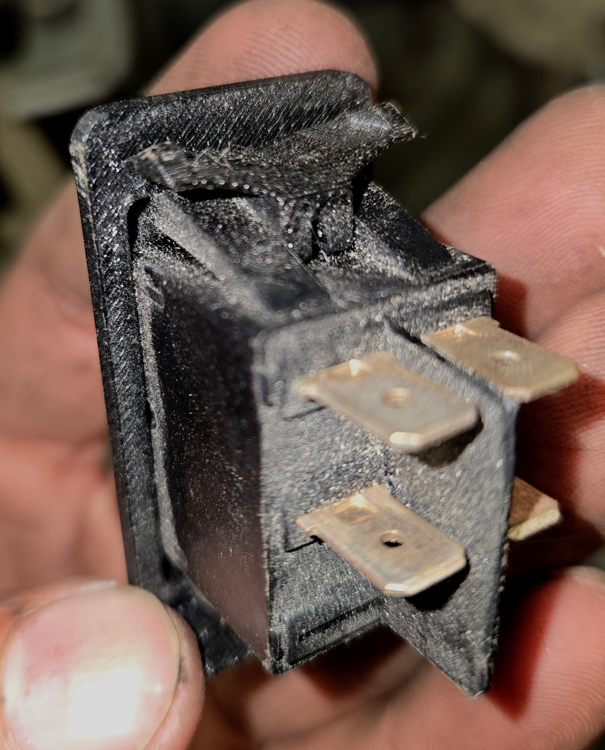
Figuring out how to remove the back was a real struggle, and my methods left quite a few scars on the perimeter of the shell.</p>

<p><img src="/assets/img/samsung_g9/scarring.jpg" alt="Perimeter Scarring" /></p>

<p>
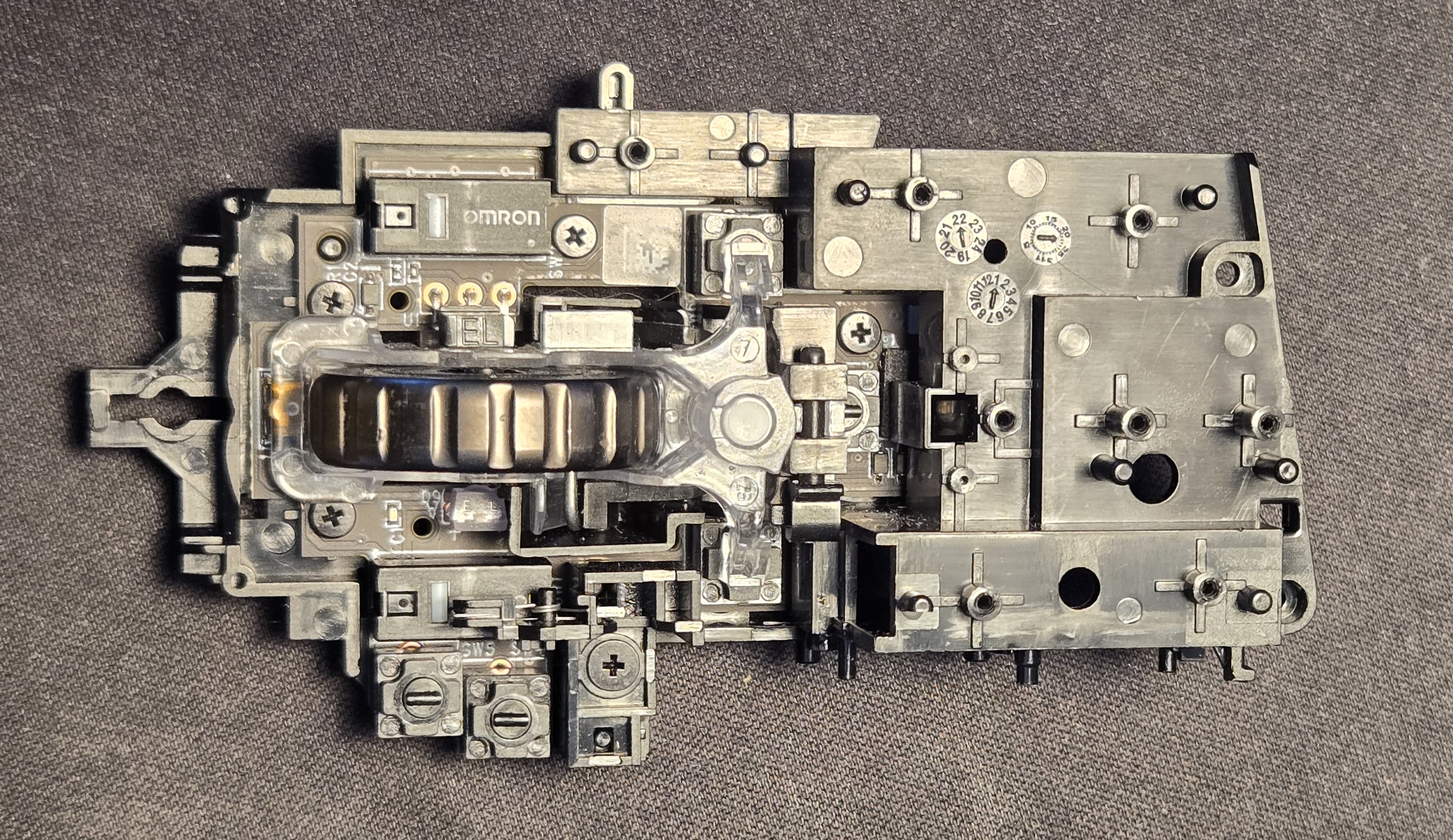
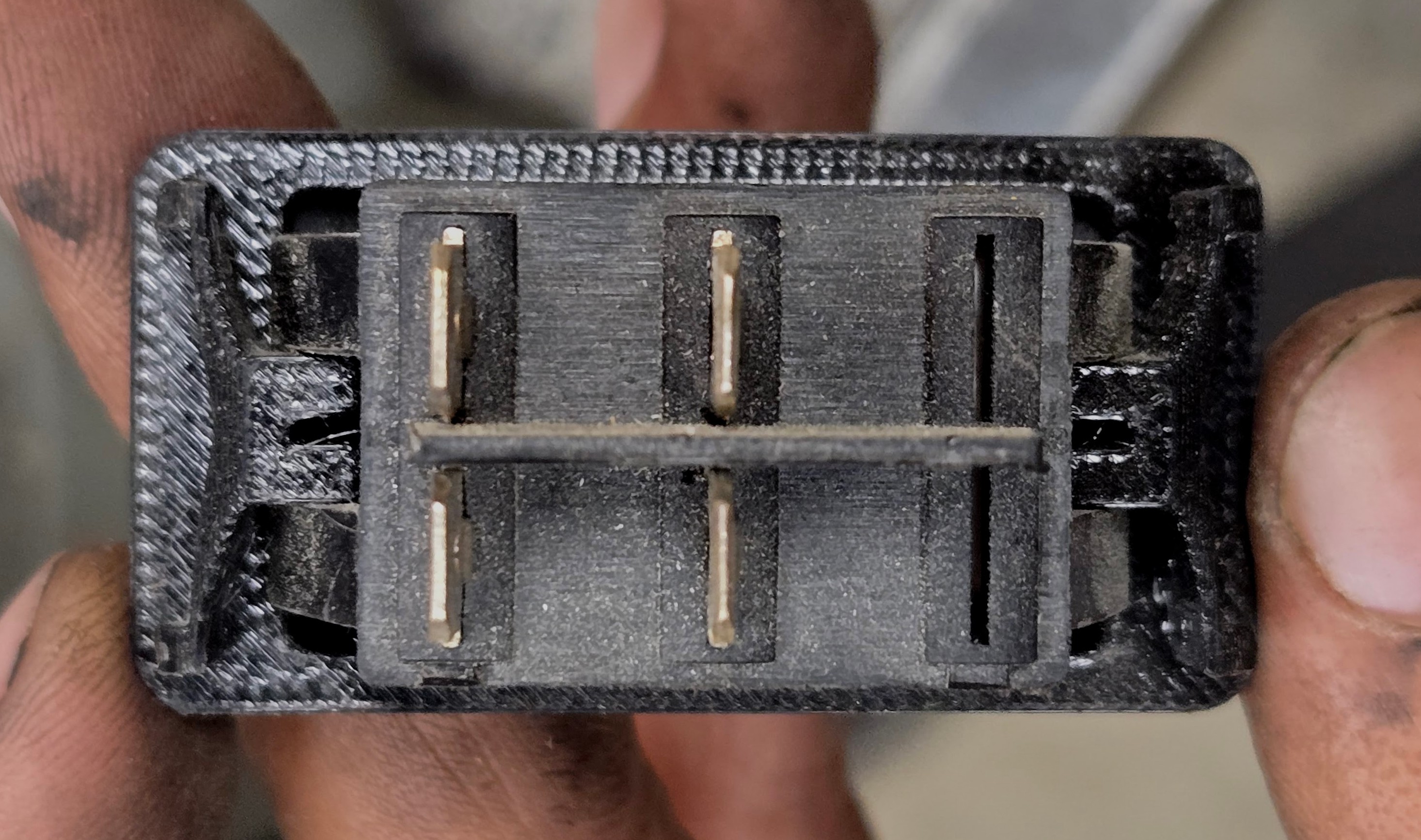
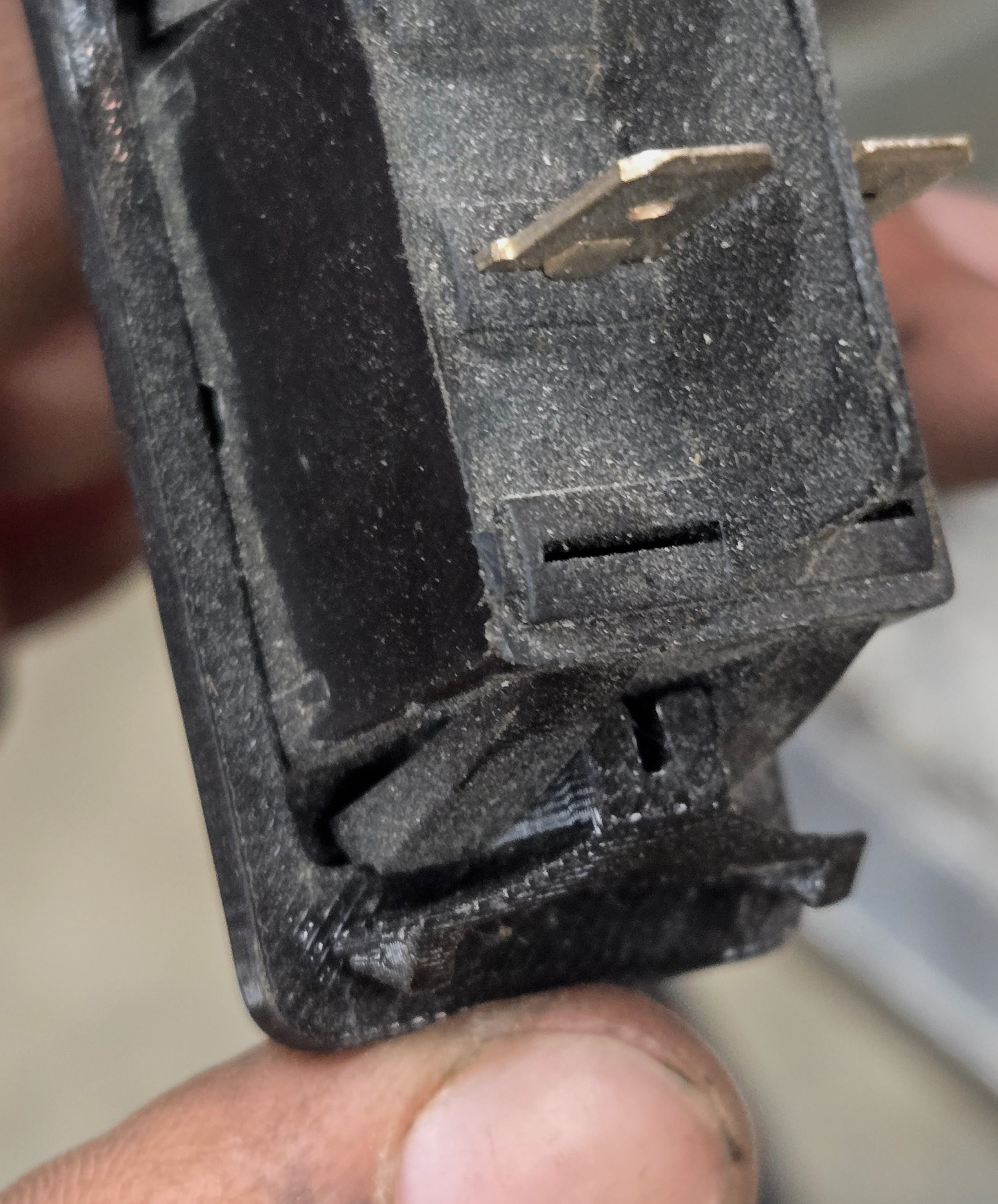
Once free of the rest of the monitor I was able to test the power supply on its own.</p>

<h2 id="a-shaky-first-step">A Shaky First Step</h2>

<p><em>Now at this point I feel it is my responsibility to tell you that this is not a tutorial, this is blog where I am chronicling my process including my poor judgement and potentially very dangerous mistakes. Do not do what I am doing. Please and thank you.</em></p>

<p>A confession: I don’t really know how switching mode power supplies work. I was always more into signal processing and embedded devices while in college; I did not take a single class on power electronics. All I knew was generally what each stage was supposed to be doing and which parts I shouldn’t touch.</p>

<p><img src="/assets/img/samsung_g9/PCB_top.webp" alt="PCB Top" /></p>

<p>So naturally, I turned to the LLM.</p>

<p>I was probably out of free Claude tokens when I started this because I started my diagnostic with Deepseek:</p>

<blockquote>
  <p>
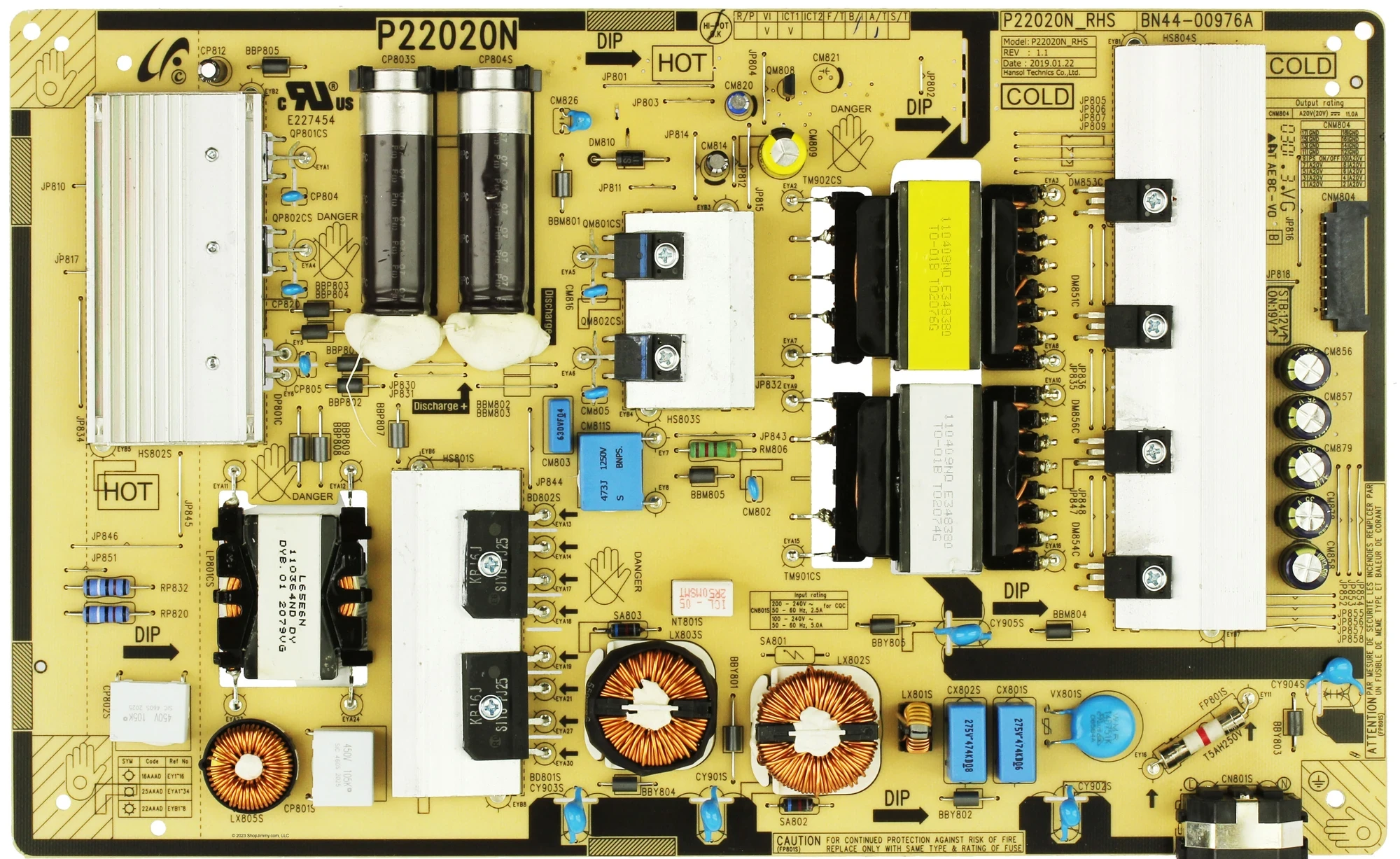
I am repairing a Samsung G9 Odyssey power supply P/N BN4400976A. After the initial visual inspection (no obvious faults, e.g. burning or corrosion), I connected it to line voltage. There is no voltage at CNM804, nor at JP818. In fact, the fuse, FP801S (T5AH250V) has blown and the board is not powering up at all. 
Am I correct in assuming that I first ought to just replace this fuse? My thinking is that even if there is a fault elsewhere, I cannot determine that until I replace it.</p>
</blockquote>

<p>The numbers probably don’t mean all that much to you, but Samsung seems to have a fairly standard topology (maybe I’m using that word incorrectly) across all of their television/monitor switching mode power supplies, and I figured the numbers might yield useful searches for the LLM. Just for fun let’s keep track of the fuses. This one is <strong>Fuse 0</strong>.</p>

<p>Anyhow, I asked Deepseek to summarize its response to this prompt, that it may fairly represent itself in this public article:</p>
<blockquote>
<h3>What the AI Said (That I Absolutely Should Have Listened To)</h3>

<p>In its infinite robot wisdom, my AI assistant laid out a perfectly sensible, safety-obsessed repair plan. It kindly informed me that:</p>

<p>A blown fuse is a symptom, not the problem. Replacing it without finding the root cause is like putting a new bandage on a severed artery and going for a jog.</p>

<p>It then begged me — in that polite, emotionally neutral way that AIs have — to do the following:</p>
<ul>
    <li>Test the bridge rectifier and switching FETs first (because they're almost always the actual culprits).</li>

    <li>Build a Dim Bulb Tester — a magical device involving an incandescent light bulb that limits current and prevents catastrophic failure. The assistant described it as "the most important tool for repairing switch-mode power supplies."</li>

    <li>Do NOT, under any circumstances, just replace the fuse and plug directly into mains. It used all-caps and bold text. It mentioned "loud pop," "more component damage," and "another blown fuse."</li>
</ul>
</blockquote>

<p>I am not a smart man. I saw that the switching MOSFETs were shorted, so I ordered replacements and soldered them in, replaced the fuse (<strong>Fuse 1</strong>). I had a unfounded sense of optimism that this was all that had gone wrong. I did not read a short at line and neutral of the cord input. I did not check anywhere else:</p>

<blockquote>
  <p>Alright, I found the transistors QP801CS and QP802CS to be shorted. they are model MMF60R190QS. I removed them and replaced them with GC20N65F, an equivalent transistor, as well as changed out the fuse. 
I realize I probably should have used a Dim Bulb Tester, but I got hasty and just plugged it in to Line voltage. 
There was arcing across the transistor area, seemingly local to QP802CS. The board is pretty scorched but the transistors themselves seem fine. Caps CP804 CP820 and CP805 all show sign of scorching, from the inside out.</p>
</blockquote>

<p>In my defense it was getting quite late.</p>

<p>You may witness the carnage for yourself:</p>

<p><img src="/assets/img/samsung_g9/burnt_caps.jpg" alt="Burnt Caps" /></p>

<p>And Deepseek’s summary of itself (Good lord, one model that really needs to learn some brevity):</p>
<blockquote>
<ul>
<li>"Stop. Disconnect immediately."</li>
<li>The original shorted FETs were victims, not the cause. The real killer was probably the PWM controller IC.</li>
<li>Those exploding capacitors? Innocent bystanders.</li>
<li>Scrub carbon tracks off the PCB. Sniff for burnt components. Desolder and retest everything.</li>
<li>At this point, just buy a replacement board.</li>
</ul>
</blockquote>

<p>That last point was enough to turn me off Deepseek for the time being, I’m no quitter.</p>

<h2 id="sound-footing">Sound Footing</h2>

<p>
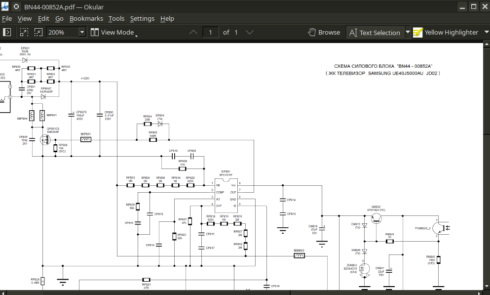
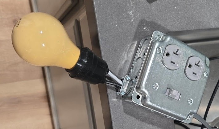
I spent a couple of days reading up on the design of the power supply and repair/diagnostic methodology specific to TVs. I managed to track down a schematic for a very similar power supply board, a BN44-00852A. I even built a <strong>dim bulb tester</strong>.</p>

<p><img src="/assets/img/samsung_g9/schematic.png" alt="Schematic" /></p>

<p><em>Dim bulb tester is really kind of GOATed. It’s a simple device, an incandescent bulb in series with an outlet, with a switch for convenience. If there is a short in the device being tested, the bulb glows brightly, and the current draw causes a large voltage drop across the bulb, protecting the tested device. In the case of my power supply, the bulb should initially glow brightly as the inrush current charges the big caps, and then dim.</em></p>

<p><img src="/assets/img/samsung_g9/dim_bulb_tester.jpg" alt="Dim Bulb Tester" /></p>

<p>Having constructed the tester and cleaned the PCB, I decided to switch to an LLM with a more indomitable spirit, Claude.</p>

<p>I related to it most of what I have here so I won’t repeat it.</p>

<p>Claude acknowledged the failed switching FETs and caps, but urged me to pursue faults in the power factor correction (PFC) circuit, especially the controller IC.</p>
<blockquote>
  <p>Power factor is the ratio of real power vs apparent power. In a circuit with poor/low quality factor, the supply “sees” more power drawn than is actually used by the device. Extra power “sloshing” back and forth from supply to device is called reactive power. The PFC circuit brings voltage and current closer to being in phase with one another, increasing efficiency.</p>
</blockquote>

<p>Now, in my research the week prior, I watched a video of an old British man repairing a similar power supply just by cutting the trace connecting the switching FETs to the controller ICs. See, the total current draw of a monitor, even one as big and bright as this, is not that great. These PFC circuits are implemented to meet certain regulatory standards about efficiency that are just not that important to me. (The extra cost of the reactive power this monitor draws is not greater than what I’d pay for these discontinued ICs or god forbid a new power supply board from Samsung.)</p>

<p>But we’re getting ahead of ourselves, is it even bad?
I desoldered the resistors connecting the bridge rectifier to the switching circuit, RP832 and RP820, and began probing. Based on ~3 hours of scraping silicone and probing tiny resistors, no. The PFC circuit is fine.</p>

<p>There was another whole bit where Claude hallucinated some specs about my replacement transistors and threw a little fit until I gave it the relevant sections in the datasheets.</p>

<p>I bought a new recovery diode just to be safe, and replaced the burnt ceramic capacitors with new ones. Reading the tiny letters on the bodies was a special hell for my weak eyes; several times during this little project I considered purchasing a microscope.</p>

<p><img src="/assets/img/samsung_g9/cp805.jpg" alt="CP805" /></p>

<p>Everything was testing just fine so I put the resistors back in, screwed down the heatsink, and put in a new fuse (<strong>Fuse 2</strong>). This time I plugged it into the dim bulb tester.  I switched it on for ~5 seconds no great effect (a good sign). The bulb seemed fairly, dim, and stayed dim throughout the duration.
I unplugged it. None of the components seemed warm. The big caps are not even charged to one volt (these are going to reach 300-something volts in normal operation).
Round two, same setup but with my multimeter test leads checking the input voltage to the PSU. Switching it on, I have 4V, dropping to 3.8. Bulb brightness is unchanged and the voltage remains steady.</p>

<p>I think we ought to try plugging it into mains.
And…  still no dice. Less dramatic this time, but the fuse fizzled out just the same.</p>

<h2 id="what-gives">What gives?</h2>

<p>This one really threw me for a loop for quite a while.
I was probing once again. Something between putting the PSU back together and plugging it in had caused a short in the PFC circuit. Specifically I could measure a short between the legs of the big filter caps (remember the ones that were not charging!). How had this happened? The caps are rated for 600V and had tested perfectly fine just minutes ago. They looked perfectly fine, not bulging, not warm. I desoldered them and tested them alone. Perfectly fine. WTF.</p>

<p>OK, so it’s not the capacitors, but something parallel to the capacitors.
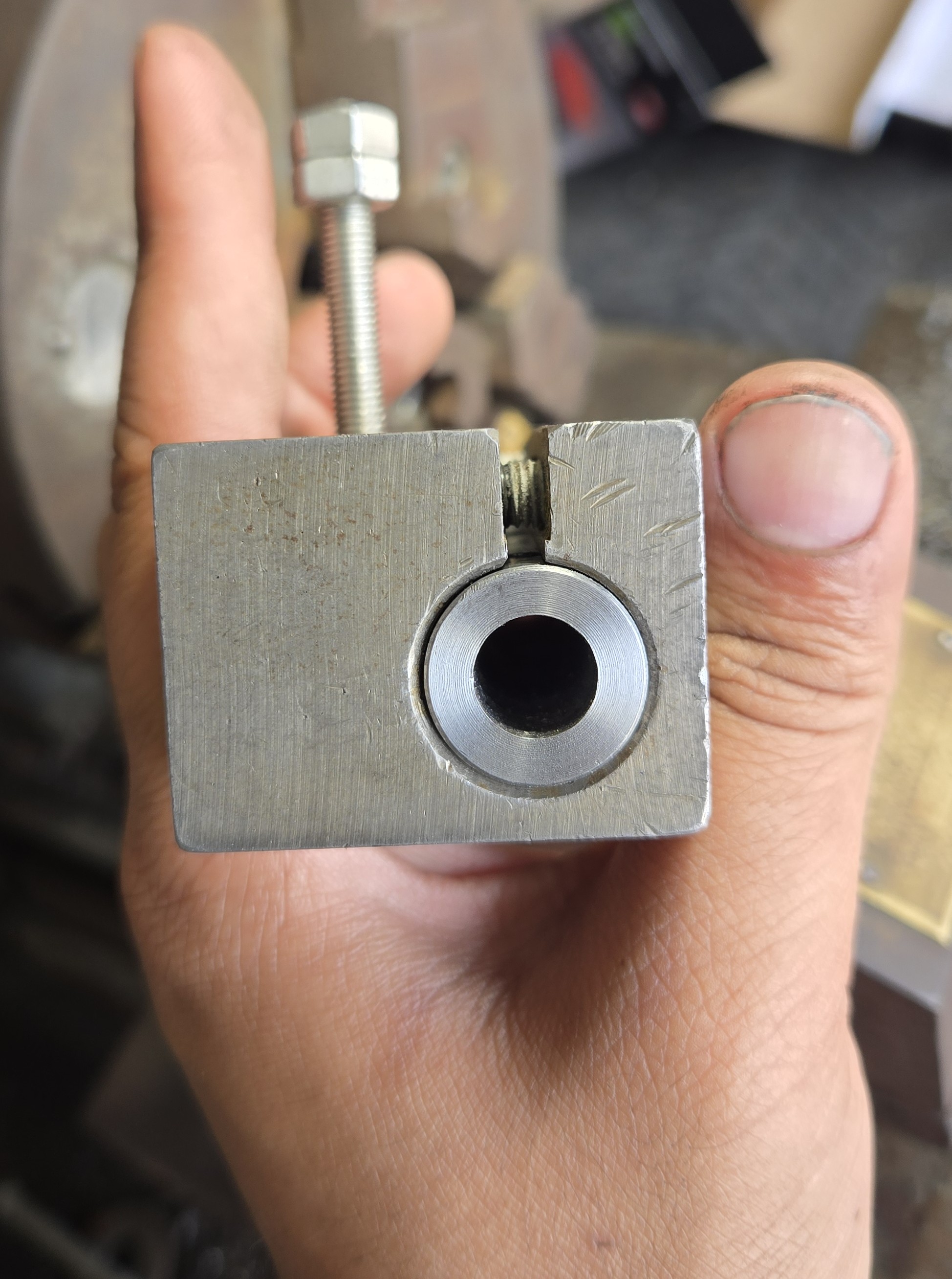
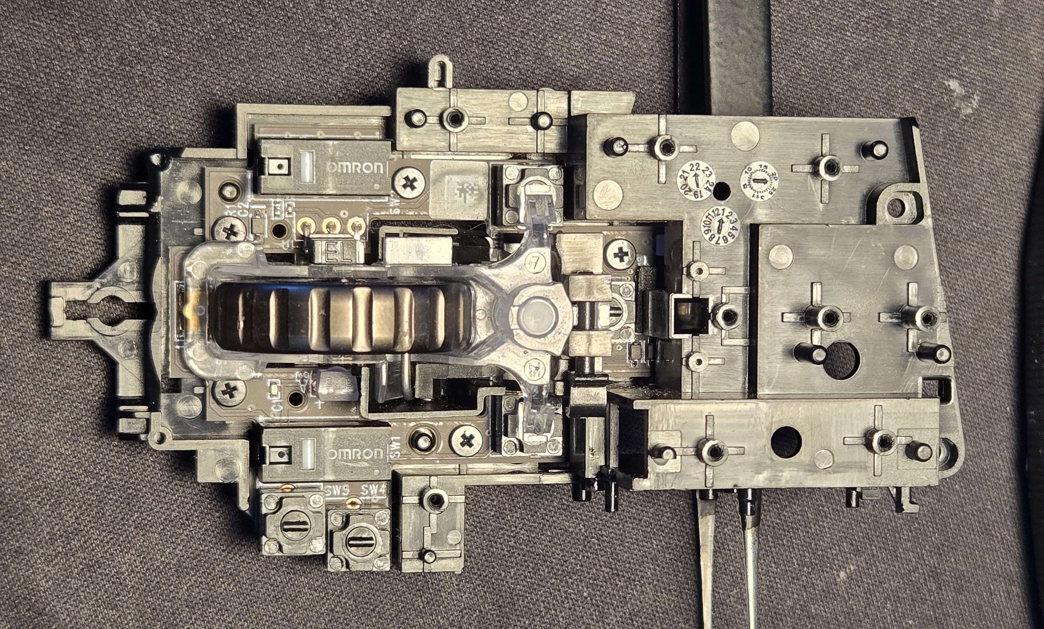
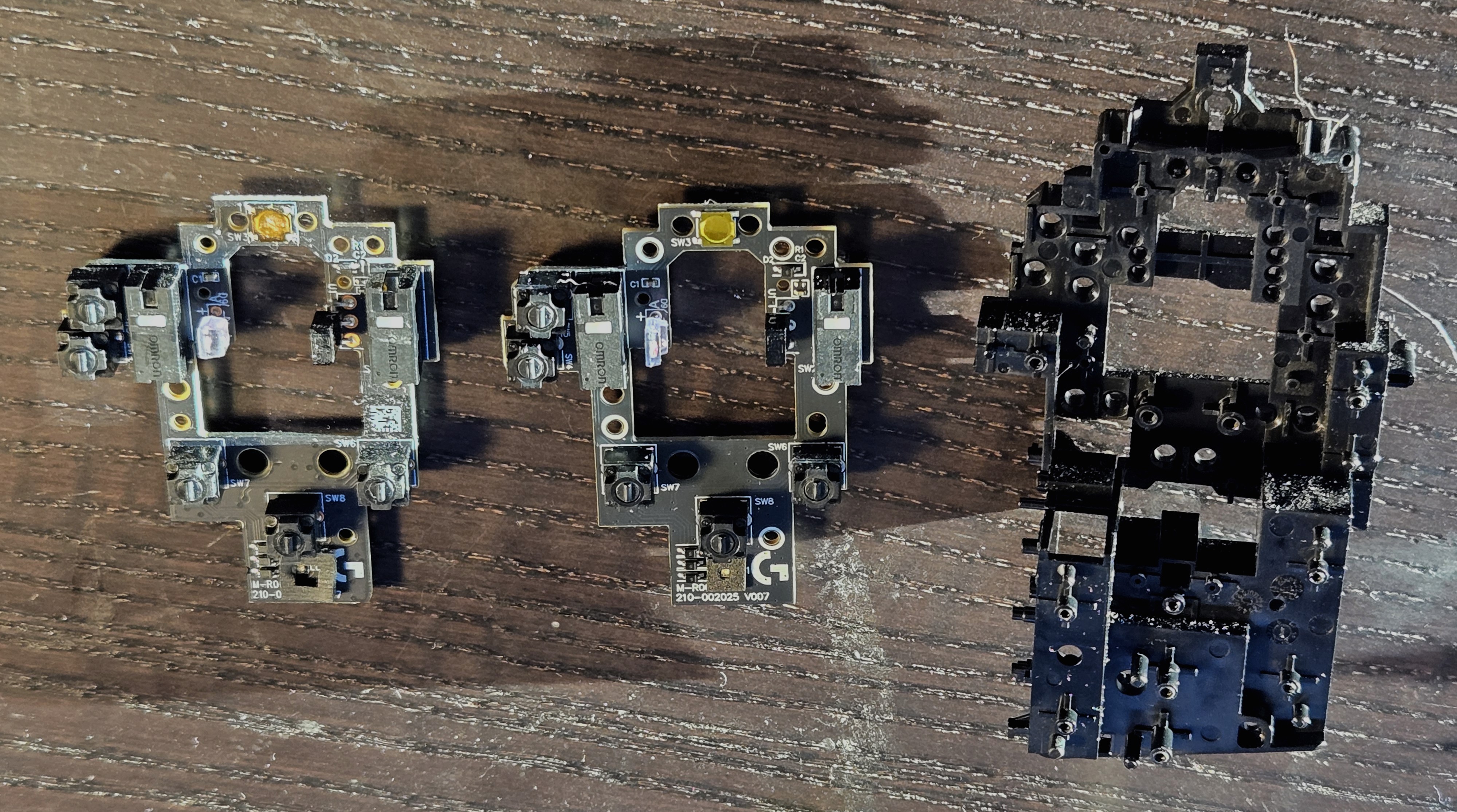
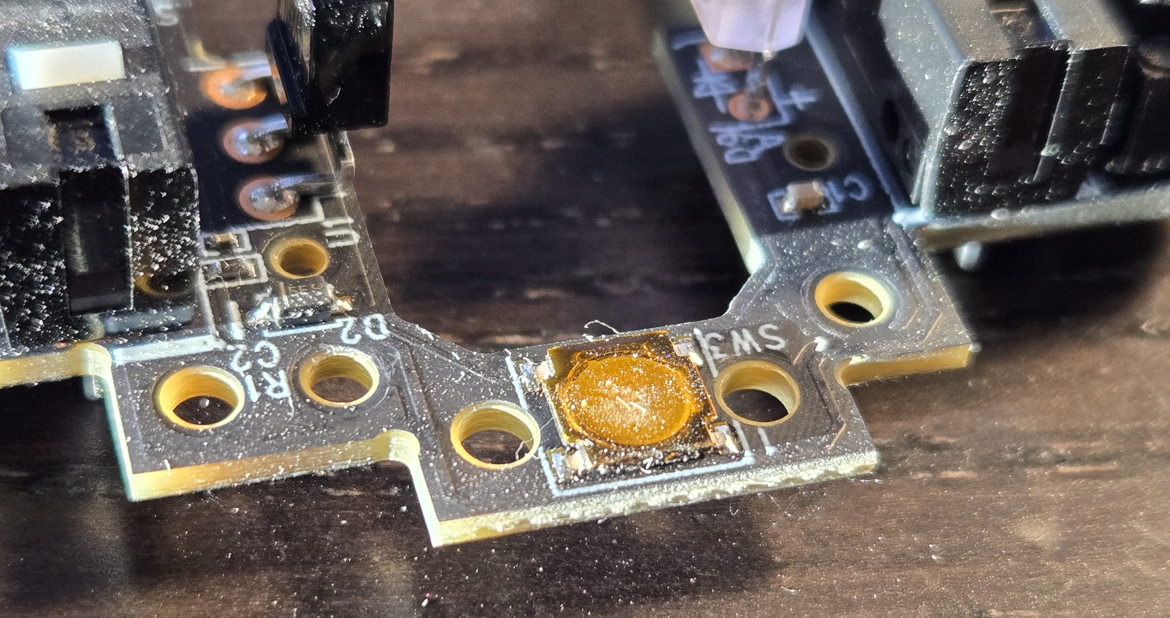
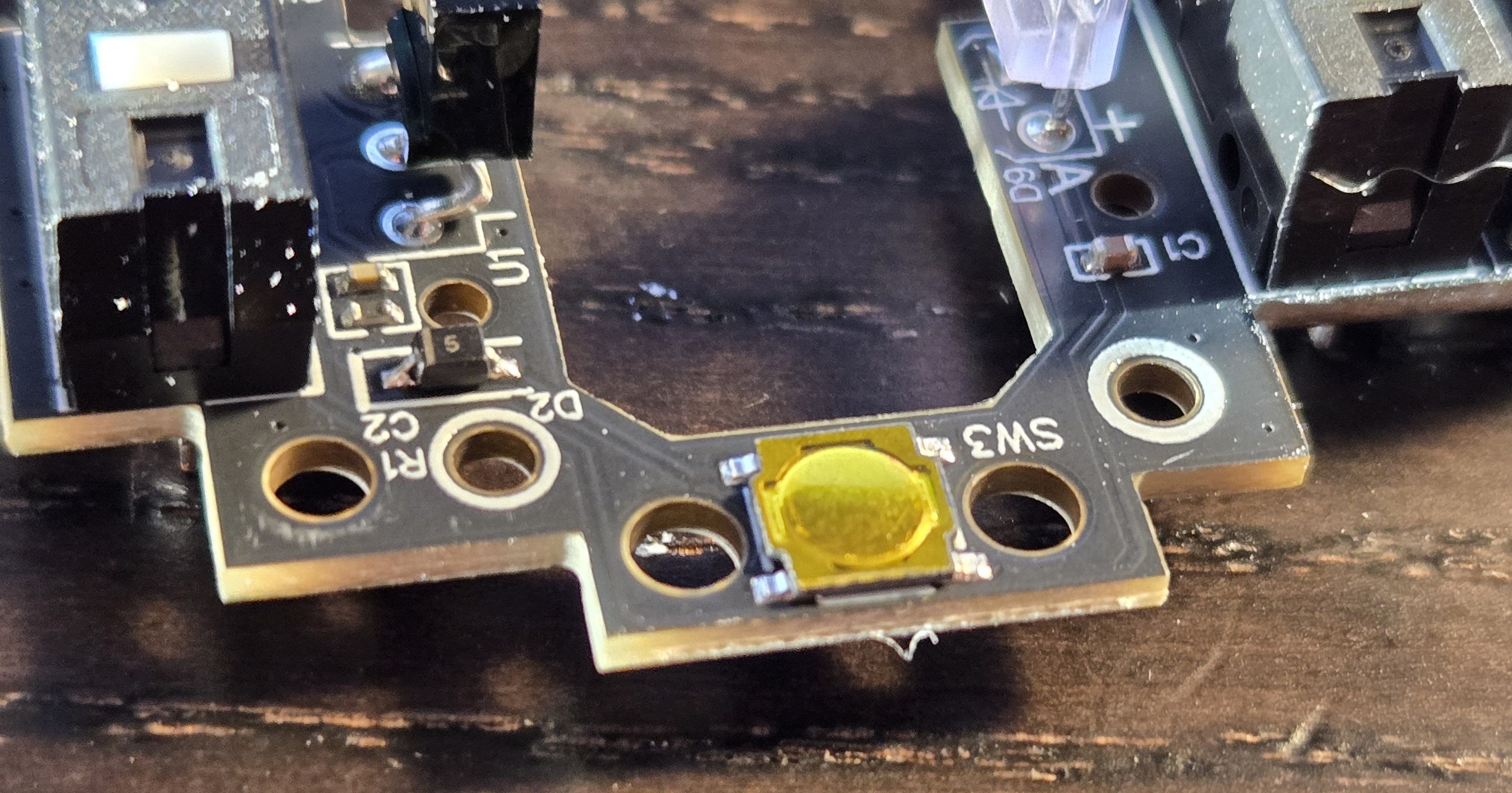
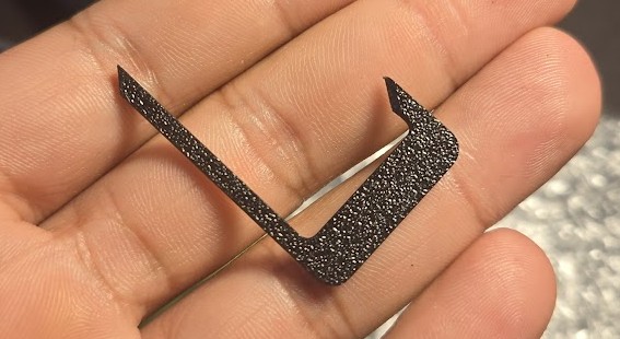
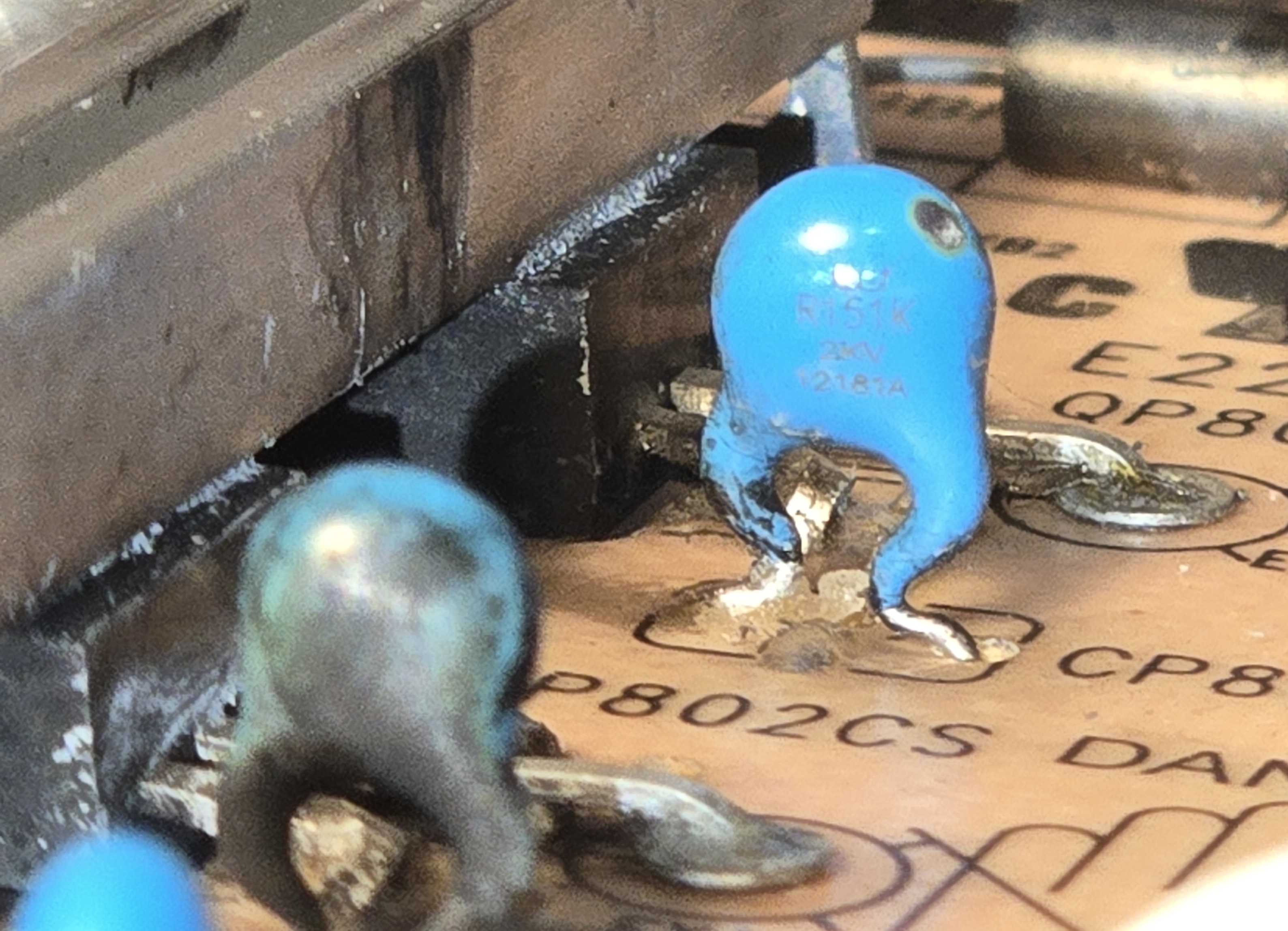
Let’s take a look at the bottom of this PCB:</p>

<p><img src="/assets/img/samsung_g9/PCB_bottom.webp" alt="PCB Bottom" /></p>

<p>
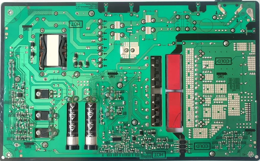
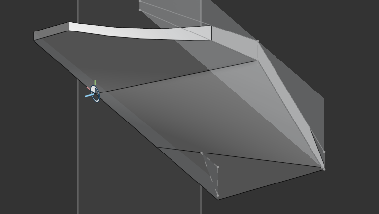
I’m not quite even sure how I got to this other than pure dumb luck, so I’ll illustrate something for you.</p>

<p>Here is the current path from the filter/rectifier stage to the filter caps of interest:
<!-- ![PCB Detail 1](/assets/img/samsung_g9/PCB_bottom_detail1.webp) --></p>
<center><img src="/assets/img/samsung_g9/PCB_bottom_detail1.webp" /></center>
<p><br />
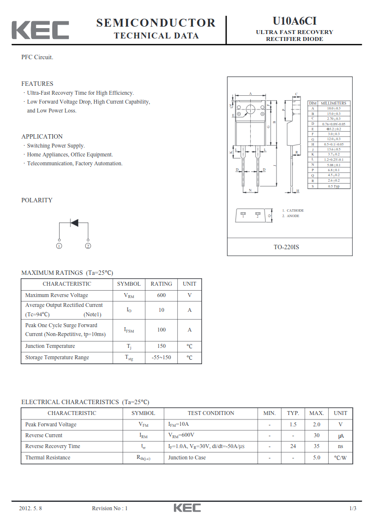
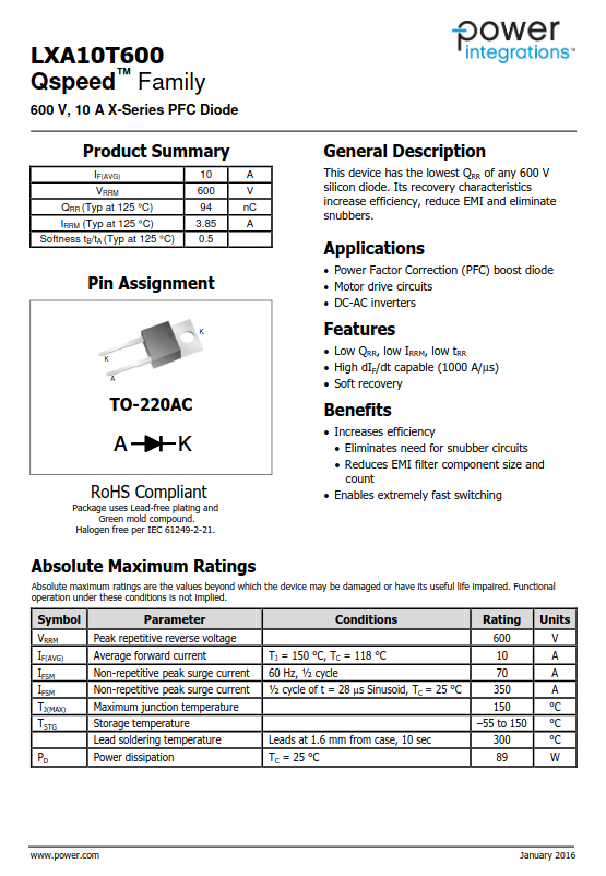
And now, two datasheets, the original U10A6CI diode and the replacement LXA10T600:</p>

<div style="display: flex;">
  <img src="/assets/img/samsung_g9/U10A6CI.png" style="width: 50%;" />
  <img src="/assets/img/samsung_g9/LXA10T600.png" style="width: 50%;" />
</div>
<p><br />
<!-- ![U10A6CI Datasheet]({ ![LXA10T600 Datasheet]() --></p>

<p>
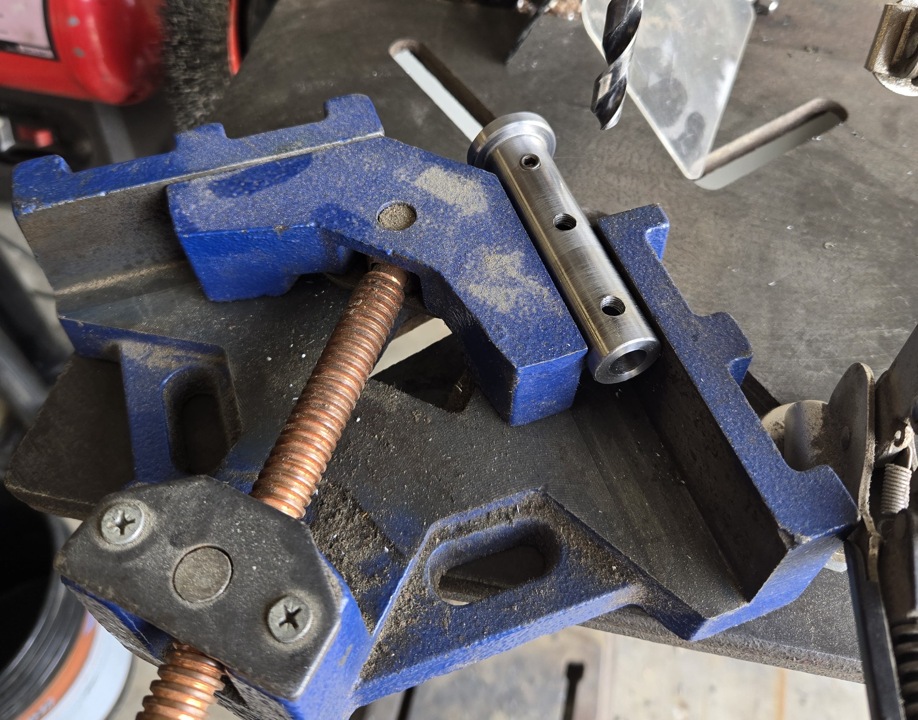
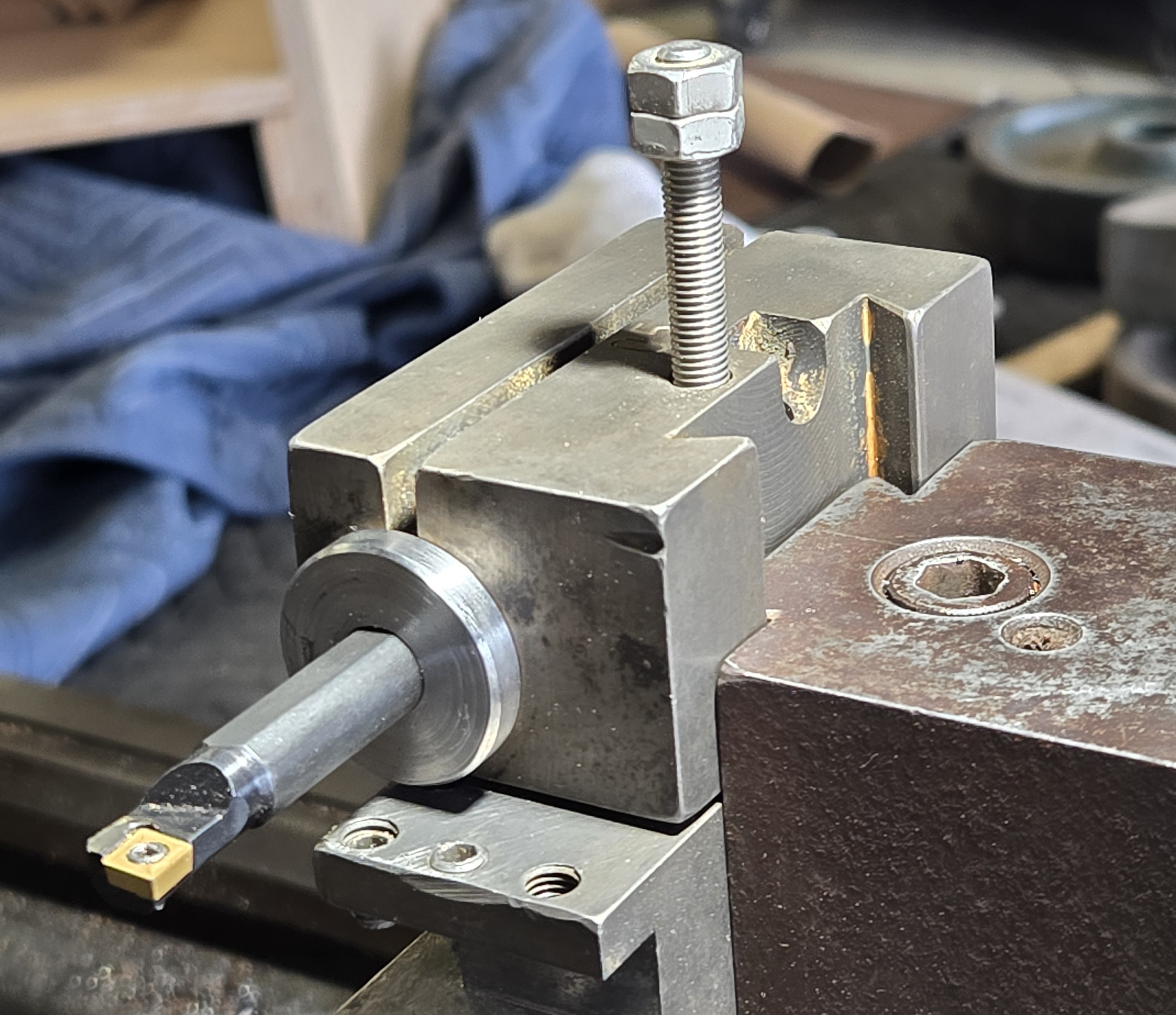
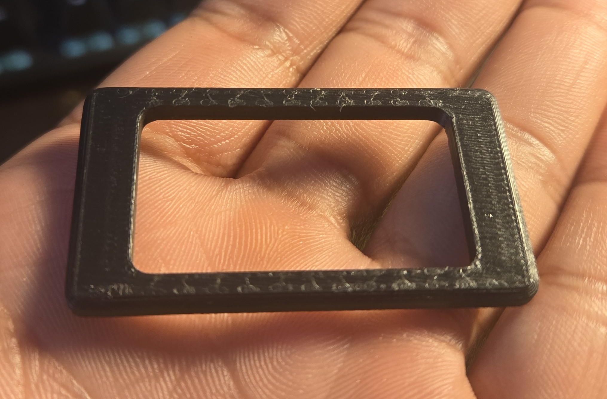
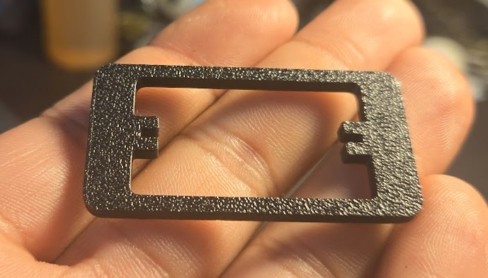
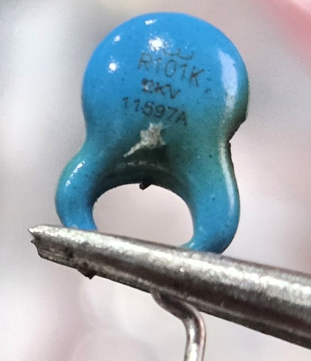
And just for good effect, observe them irl:
<img src="/assets/img/samsung_g9/diodes.jpg" alt="Diodes SBS" /></p>

<p>
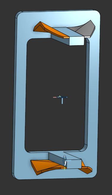
Noticing? Maybe not, let me make it explicit with another illustration:
<!-- ![PCB Detail 2](/assets/img/samsung_g9/PCB_bottom_detail2.webp) --></p>
<center><img src="/assets/img/samsung_g9/PCB_bottom_detail2.webp" /></center>
<p><br />
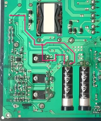
The replacement diode’s mounting flange is electrically connected to the cathode (K) of the diode itself.</p>

<p>The path through the capacitor doesn’t “matter” except to illustrate why the cap didn’t charge, the big issue is the cathode getting that high voltage input instead of what it’s supposed to get at the output of the cap.</p>

<p>The simplest solution to this problem was to just cut one of the leg of the heat sink, simple enough with some snips, and to desolder the leg from the board. The heatsink is soldered in three other places, and I did check this time that the heat sink was not electrically connected to any other part of the circuit.</p>

<blockquote>
Claude seems to have gotten understood a portion of what happened before I tried it with mains. As I described, the big caps had not charged much at all when connected to the dim bulb tester.

It remarks:
<blockquote>
<p>✓ No catastrophic shorts (good!)</p>
<p>✓ Input filter is okay</p>
<p>✗ PFC stage is not starting up</p>
<p>✗ No caps charging = PFC controller (ICP801S) isn't switching</p>
</blockquote>

Continuing:
<blockquote>
The ICP801S needs a certain startup voltage (typically 12-18V) on its VCC pin before it begins operation. With only 4V at the AC input through the dim bulb, there's not enough voltage getting through the startup circuit to wake up the PFC controller.
</blockquote>
Claude asked that I attempt this once more with a larger bulb, a 120W, to get more current voltage to the PFC circuit, but I really could not be arsed to drive to the hardware store again.
</blockquote>

<p>At this point, I was not sure I could trust anything. Everything seemed to check out. I replaced the transistors for good measure. A new fuse was installed (<strong>Fuse 3</strong>).</p>

<p>I tested it with the dim bulb tester one more time. Everything looked good.</p>

<p>And on mains, all good. The fuse did not blow. The output pins produced their low voltage, and when the standby pin was energized, the voltage went up to 19.2 V.</p>

<p>Time to put it back on the monitor.
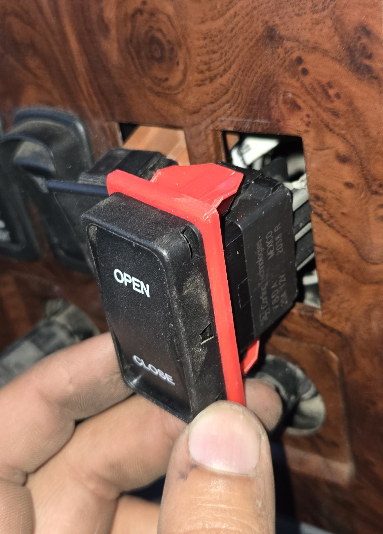
</p>

<h2 id="success">Success</h2>

<p>This was really an nerve-wracking moment for me, but moments after the monitor was plugged in, the power light shone on. I pressed it once, and a menu told me there was no source detected.</p>

<p>And connecting it to my laptop:</p>

<p><img src="/assets/img/samsung_g9/working.jpg" alt="Working" /></p>

<p><strong>
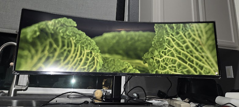
And I am typing this very article at this very monitor at this very moment.</strong></p>

<p><img src="/assets/img/samsung_g9/action.jpg" alt="WIP" /></p>

<p>
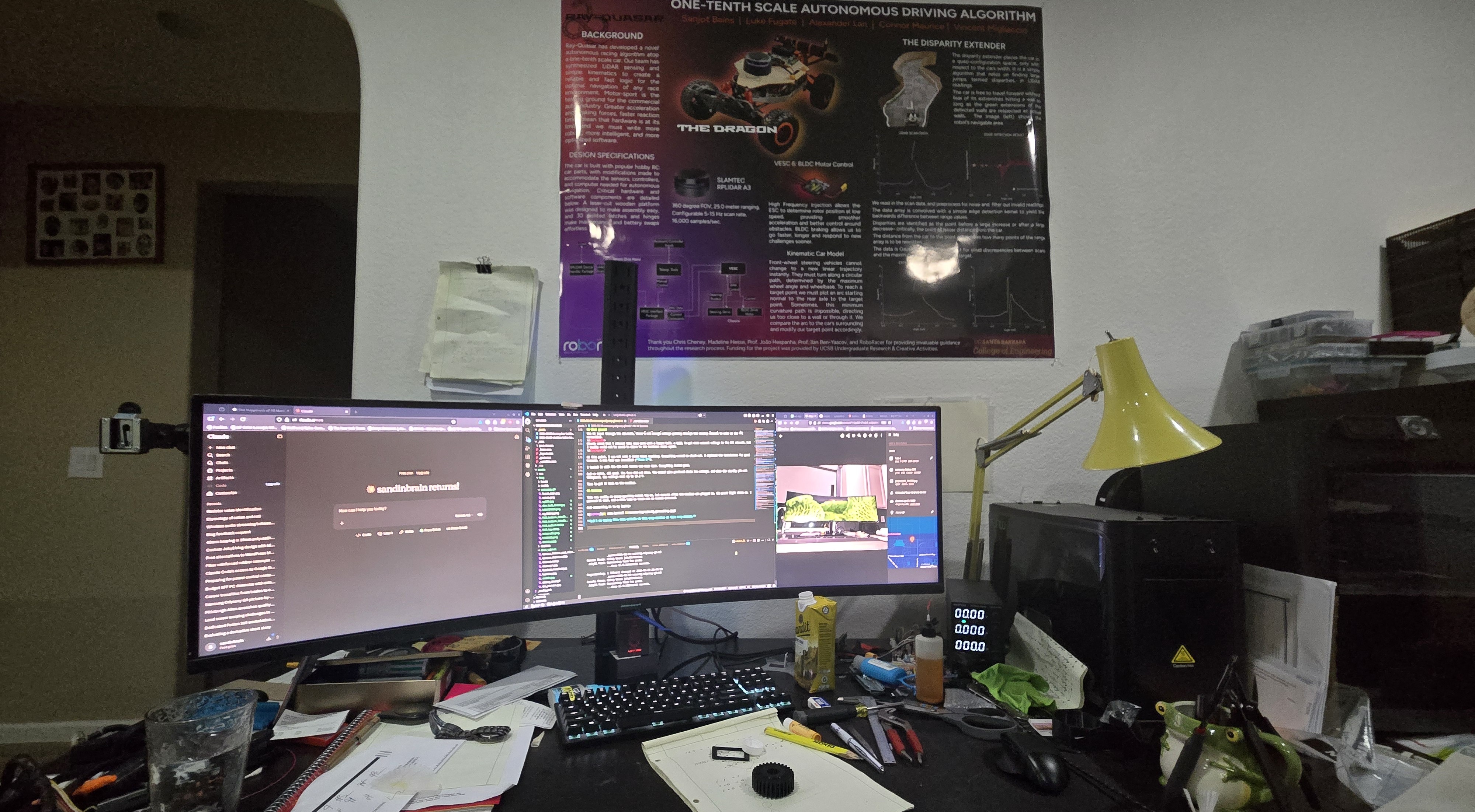
I’m not much of a gamer, so I’ll never really get the most out of it, and I do sort of miss the DPI of my 27” 4K monitor this is replacing, but this monitor provides extraordinary real estate for productivity. Two 27” monitors would have the same amount of screen, but the middle bezel destroys that central prime real estate. I think it’ll be sticking around.</p>]]></content><author><name></name></author><category term="electrical" /><category term="repair" /><category term="PCB" /><category term="computer" /><summary type="html"><![CDATA[Snatched It Off the Stork on a Friday On January 16, a day much like any other, I was browsing Facebook Marketplace as I am want to do several times a day; one must always be optimizing his dealflow. This ordinary day was made quite special by my finding for sale a Samsung LC49RG90SSN– a Big F***ing Monitor– for $90, broken of course. But pay keen attention to the description:]]></summary></entry><entry><title type="html">Maiyaan Stool</title><link href="http://www.sandinbrain.com/2025/11/25/maiyaan-stool.html" rel="alternate" type="text/html" title="Maiyaan Stool" /><published>2025-11-25T00:00:00+00:00</published><updated>2025-11-25T00:00:00+00:00</updated><id>http://www.sandinbrain.com/2025/11/25/maiyaan-stool</id><content type="html" xml:base="http://www.sandinbrain.com/2025/11/25/maiyaan-stool.html"><![CDATA[<p>A <em>maiyaan</em> is a sort of bridal shower that precedes Punjabi weddings. The prospective bride/groom is sat in front of their family on a low stool, shaded by a red embroidered <em>chunni</em>, and rubbed down with a paste made of turmeric, flour, and mustard oil, a sort of ancient bronzer.</p>

<p>Now of course with modern cosmetics and the like, this ceremony is entirely ceremonial, but it persists to fulfil the aesthetic “bigness” of the Punjabi wedding, and therefore has evolved to an even larger, more ornate, more ostentatious event.</p>

<p>My sister’s was to take place in a transparent tent, strung with light braids and chandeliers, with a set: carpets, an archway, draperies, floral arrangements.</p>

<p>I was not satisfied with the stool. Maiyaan stools are typically of the typical Indian wooden stool style, a board held up by two boards across its length:</p>

<!-- Fatta Picture -->
<p><a href="">Simple Low Stool</a></p>

<p>Of course they are usually wrapped in a velvet and glittering gold ribbon, but still figural-ly unimpressive.</p>

<p>I’ve long admired the cabriole leg footstools typical of Victorian furniture, and I figured this would be a great opportunity to use that figure. In fact, I started design/construction with a sketch of the leg profile.</p>

<!-- Leg sketch -->
<p><img src="" alt="Leg Profile Sketch" /></p>

<p>I modeled this component as well, that I may have the piece in my hand to critique its curves.</p>

<!-- Fusion Embed -->
<p>Fusion Embed iframe</p>

<p><img src="" alt="Printed Leg Model" /></p>

<p>Now we have to take a slight detour to talk about lumber. I wanted this piece to have special sentimental significance for my sister, as it is a symbol of her childhood home. The houses in our neighborhood all feature a Chinese Pistache in the sidewalk strip. Unfortunately ours, after 20 years was showing signs of disease, so I cut it down last year. I’d been keeping the trunk, ~12” of heartwood, in the shop for a special project and this seemed quite right.</p>

<p>Fruit tree wood is always a bear, tough, figured, with bark inclusions and young limbs swallowed inside, and this was no different. I tried splitting it into boards to no avail. I ended up ripping it into quarters with the chainsaw, before taking it to the bandsaw to resaw.</p>

<p>Here are some small boards left over from the project:</p>

<p><img src="" alt="Chinese Pistache Boards" /></p>

<p>I printed off cutting templates for the leg profile and glued them onto the stock, and cut off the waste at the bandsaw, now with a 1/8” blade. This blade has far too many teeth inside the kerf, a recipe for binding and burning, but I took it slow and it all went without disaster.</p>

<p>The roughed legs were joined and glued to the stretchers with dowels. The stretchers had the joint chamfer roughed before glue up.</p>

<p>I shaped the round tops of the stretchers after gluing up. I wanted to incorporate any inconsistencies in the leg shapes smoothly from leg to leg, simple enough just by planing from one end to the other until I can take a continuous shaving tip to tip.</p>

<p><img src="" alt="Shaping Stretchers" /></p>

<p>Perhaps the worst part of this project was creating the chamfers on the joint faces.
Procedure:
 I used a groove carving tool to rough out the shape.
 I used a round file to take down the ridges caused by the grooving tool.
 I cleaned the file’s witness marks with sandpaper wrapped around a dowel. At some places the tearout on the interior was too great to remove entirely, but this is a foot stool; one would literally have to be a mouse to see this.</p>

<p>Now comes time for the upholstered top. I always dread upholstery, there are too many variables, and with a piece as small as this, any unevenness along the edge would readily reveal itself.</p>

<p>I selected this fabric for the cushion, keeping with the red and gold theme of an Indian wedding.</p>

<p><img src="" alt="Fabric Sample" /></p>

<p>I used the denser blue foam and poly batting to ensure a smooth surface. I glued these down to a plywood panel, chamfered to ensure no hard edge would poke through the upholstery. The fabric is wrapped and stapled, a tedious process that I did in fact do twice.
I covered the bottom in a grey felt to disguise the horrible stapling I did.
I inserted a metal button and pulled it down with a twist of fencing wire through the plywood panel.</p>

<p>The frame was finished with boiled linseed oil and wax.</p>]]></content><author><name></name></author><category term="woodworking" /><category term="furniture" /><category term="upholstery" /><category term="footstool" /><summary type="html"><![CDATA[A maiyaan is a sort of bridal shower that precedes Punjabi weddings. The prospective bride/groom is sat in front of their family on a low stool, shaded by a red embroidered chunni, and rubbed down with a paste made of turmeric, flour, and mustard oil, a sort of ancient bronzer.]]></summary></entry><entry><title type="html">Mack CX13 Hookup Light Wiring Box</title><link href="http://www.sandinbrain.com/2025/10/12/mack-light-box.html" rel="alternate" type="text/html" title="Mack CX13 Hookup Light Wiring Box" /><published>2025-10-12T00:00:00+00:00</published><updated>2025-10-12T00:00:00+00:00</updated><id>http://www.sandinbrain.com/2025/10/12/mack-light-box</id><content type="html" xml:base="http://www.sandinbrain.com/2025/10/12/mack-light-box.html"><![CDATA[<p>Sometimes at work I am allowed to exercise an iota of creativity, and this was one of those instances I was tasked with replacing the hookup light with a brighter LED one on a MACK CX13.</p>

<p>The new lamp is a little light bar on a swivel mount. The owner of the truck lost the mounting hardware, but the threaded holes are intact.</p>

<p>I cut and welded some unidentified stainless steel brackets onto the top bar, where one might tie up his trailer hookup lines.</p>

<p><img src="/assets/img/mack/light_bar.jpg" alt="Light Bar" /></p>

<p>The old lamp was round and mounted low on the cab with three screws. I knew I could use the existing bolt holes to enclose the lighting wiring.</p>

<p>I took a picture of the cab and some measurements of the hole spacing, and brought it into Fusion.</p>

<!-- ![Bolt Pattern](/assets/img/mack/bolt_pattern.jpg) -->
<center><img src="/assets/img/mack/bolt_pattern.jpg" style="width: 50%;" /></center>
<p><br /></p>

<p>Some quick modeling later:
<!-- ![Completed Model](/assets/img/mack/enclosure_model.PNG) --></p>
<center><img src="/assets/img/mack/enclosure_model.PNG" style="width: 50%;" /></center>
<p><br /></p>

<center><iframe src="https://gmail3378138.autodesk360.com/shares/public/SH90d2dQT28d5b602811e5e65b88703043e3?mode=embed" width="100%" height="600" allowfullscreen="true" webkitallowfullscreen="true" mozallowfullscreen="true" frameborder="0" style="max-width: 600px;"></iframe></center>
<p><br /></p>

<p>I printed the body and the lid out of PETG on the Bambu P1S. The embedded Fusion preview also shows the TPU gasket I printed for the back side to reduce water intrusion.</p>

<h2 id="here-it-is-all-installed">Here it is all installed:</h2>

<p><img src="/assets/img/mack/installed_box.jpg" alt="Installed Box" /></p>]]></content><author><name></name></author><category term="3D printing" /><category term="wiring" /><category term="Mack" /><category term="Fusion" /><summary type="html"><![CDATA[Sometimes at work I am allowed to exercise an iota of creativity, and this was one of those instances I was tasked with replacing the hookup light with a brighter LED one on a MACK CX13.]]></summary></entry><entry><title type="html">Adapting Switches</title><link href="http://www.sandinbrain.com/2025/10/11/fog-lamp-switch-adapter.html" rel="alternate" type="text/html" title="Adapting Switches" /><published>2025-10-11T00:00:00+00:00</published><updated>2025-10-11T00:00:00+00:00</updated><id>http://www.sandinbrain.com/2025/10/11/fog-lamp-switch-adapter</id><content type="html" xml:base="http://www.sandinbrain.com/2025/10/11/fog-lamp-switch-adapter.html"><![CDATA[<p>Dump trucks require a lot of modification from the manufacturer specified equipment a dealer might sell a truck with– wet kits, tarp motor controls, extra pneumatics, &amp;c– most of which requires extra switches to be mounted in the dash. Unfortunately, none of the major high truck manufactures have been able to agree what size a dash mounted switch ought to be, so it is often up to the mechanic to source the proper switch from the dealer.</p>

<p>In some cases, a kit requires a proprietary switch or, more often, a customer brings to me a kit with a switch included and does not want to pay dealer prices for a new (admittedly high quality) switch when they have a perfectly working switch right there; I recently purchased a fan override switch for a Volvo for $75.</p>

<p>In today’s case, we have a MACK CX13 in for a whole dump truck setup: a wet kit, tarp electrics, tailgate controls, and some lights. For the new fog lamps, the customer provided to me a switch, a generic from an auto parts store, that is too small to fit in the Mack’s slots.</p>

<p><img src="/assets/img/switch_adapter/rocker_switch.jpg" alt="Rocker Switch" /></p>

<p>It’s a slow weekend so I thought I’d take some time to design and 3D print an adapter.</p>

<p>The geometry on this is pretty tricky so I’ll just show you the model outright:</p>
<center><iframe src="https://gmail3378138.autodesk360.com/shares/public/SH90d2dQT28d5b602811b83dd84dbd3f49c5?mode=embed" width="600" height="600" allowfullscreen="true" webkitallowfullscreen="true" mozallowfullscreen="true" frameborder="0"></iframe></center>
<p><br /></p>

<p>The adapter is modeled off the blank cover originally set in the hole.
I modeled the perimeter of the cover and the perimeter of the new switch and printed a test piece.</p>

<center><img src="/assets/img/switch_adapter/test1.jpg" /></center>

<blockquote>
  <p>I had to cut off the test piece from the switch body, it was flexing too much to depress the clasp.</p>
</blockquote>

<p>Confirming this fit, I added in the features that wrap the rib on the switch body. The ribs on the switch body slide into the relief on the adapter and allow the winged portion that snaps into the dash to bear on the switch itself, which is made of some kind of fiber reinforced plastic. This design would not work otherwise, as the clasp does not have a large cross-sectional area and the only sensible way to print this is face down.  The name of the game when designing this kind of thing is adding in plastic wherever you can. I also increased the extrusion thickness of the face to 4mm from 3mm. This was enough that I was able to actually remove this faceplate without having to cut it off.</p>

<center><img src="/assets/img/switch_adapter/test2.jpg" /></center>

<p><br />
We can then immediately proceed to creating the clasp geometry.</p>

<p><img src="/assets/img/switch_adapter/clasp_geometry.png" alt="Clasp Wing Sketch" /></p>

<p>After an extrusion, the bottom is given a hefty chamfer such that the wing meets the face plate with infinitesimal width. We sketch a triangle on the end of the wing and extrude it inward. This wedge is the actual clasp, the wings are a spring for the clasp.</p>

<p><img src="/assets/img/switch_adapter/clasp_wedge.png" alt="Clasp Wedge" /></p>

<p>The final feature is ostensibly a chamfer, but spanning several features, so it’s performed via cutting operation.</p>

<p><img src="/assets/img/switch_adapter/input_incline.png" alt="Input Incline" /></p>

<p>The clasp of the switch body itself nestles very tightly inside the clasp of the adapter.</p>

<p><img src="/assets/img/switch_adapter/final_rear_view.jpg" alt="Final Rear View" /></p>

<blockquote>
  <p>I really ought to have blown this off before I took the pictures; it was laying around the shop for quite a while before getting installed.</p>
</blockquote>

<div style="display: flex;">
  <img src="/assets/img/switch_adapter/final_rear_34.jpg" style="width: 50%;" />
  <img src="/assets/img/switch_adapter/final_rear_upper_34.jpg" style="width: 50%;" />
</div>

<h2 id="and-in-its-final-resting-place">And in its final resting place:</h2>

<p><img src="/assets/img/switch_adapter/final.jpg" alt="Installed" /></p>]]></content><author><name></name></author><category term="3d printing" /><category term="electrical" /><category term="Fusion" /><summary type="html"><![CDATA[Dump trucks require a lot of modification from the manufacturer specified equipment a dealer might sell a truck with– wet kits, tarp motor controls, extra pneumatics, &amp;c– most of which requires extra switches to be mounted in the dash. Unfortunately, none of the major high truck manufactures have been able to agree what size a dash mounted switch ought to be, so it is often up to the mechanic to source the proper switch from the dealer.]]></summary></entry></feed>